Ultrasound diagnostic apparatus and method of controlling ultrasound diagnostic apparatus

a diagnostic apparatus and ultrasonic technology, applied in the direction of instruments, catheters, image enhancement, etc., can solve the problems of difficult to determine whether the tracheal tube is inserted into the trachea or the esophagus, and the risk of overlooking the esophageal intubation

Pending Publication Date: 2021-05-13
FUJIFILM CORP
View PDF14 Cites 0 Cited by
  • Summary
  • Abstract
  • Description
  • Claims
  • Application Information

AI Technical Summary

Benefits of technology

[0018]According to the present invention, the ultrasound diagnostic apparatus comprises an observation target detecting unit that detects the trachea and the esophagus included in the ultrasound image by performing image analysis with respect to the ultrasound image acquired by the image acquisition unit, an operation guiding unit that guides a user to operate the ultrasound probe such that the ultrasound probe is positioned at a position suitable for observing the esophagus based on a detection result by the observation target detecting unit, and an esophagus state determination unit that determines whether a tracheal tube is inserted into the esophagus detected by the observation target detecting unit, and thus it is possible to confirm the presence or absence the esophageal intubation regardless of the skill of the user.

Problems solved by technology

In the ultrasound diagnostic apparatus disclosed in JP2007-532152A, the vibration of the tracheal tube is merely visualized, and it is difficult to determine whether the tracheal tube is inserted into the trachea or the esophagus.
In particular, in a case where the esophagus is positioned on the right side of the trachea, there is a risk of overlooking the esophageal intubation.
In a case where a less skilled user confirms the presence or absence of the esophageal intubation, there is a risk of overlooking the esophageal intubation due to impatience during an emergency.

Method used


Image

  • Ultrasound diagnostic apparatus and method of controlling ultrasound diagnostic apparatus
  • Ultrasound diagnostic apparatus and method of controlling ultrasound diagnostic apparatus
  • Ultrasound diagnostic apparatus and method of controlling ultrasound diagnostic apparatus

Examples


embodiment 1

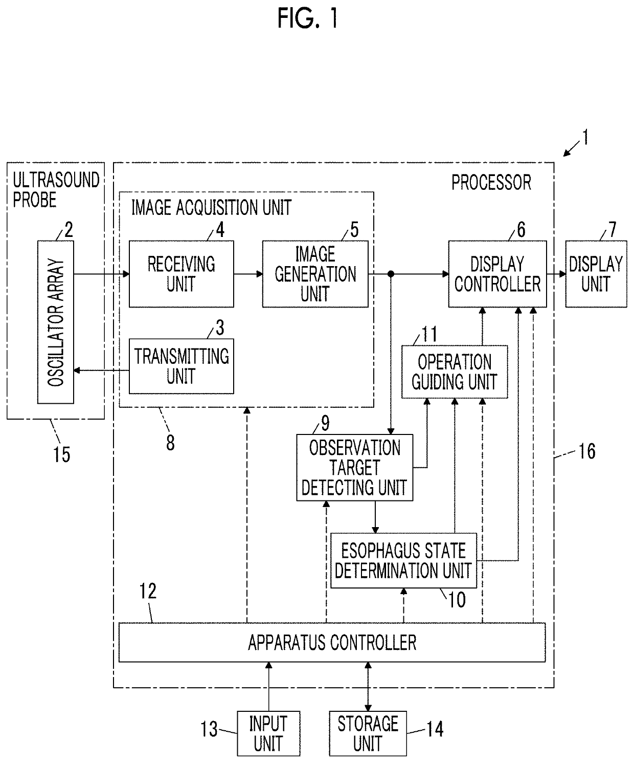
[0030]A configuration of an ultrasound diagnostic apparatus 1 according to Embodiment 1 of the present invention is shown in FIG. 1. As shown in FIG. 1, the ultrasound diagnostic apparatus 1 comprises an oscillator array 2, and a transmitting unit 3 and a receiving unit 4 are connected to the oscillator array 2. An image generation unit 5, a display controller 6, and a display unit 7 are sequentially connected to the receiving unit 4. An image acquisition unit 8 is configured by the transmitting unit 3, the receiving unit 4, and the image generation unit 5. An observation target detecting unit 9 is connected to the image generation unit 5, and an esophagus state determination unit 10 is connected to the observation target detecting unit 9. The esophagus state determination unit 10 is connected to the display controller 6. An operation guiding unit 11 is connected to the observation target detecting unit 9 and the esophagus state determination unit 10, and the display controller 6 is...


PUM


Abstract

Provided are an ultrasound diagnostic apparatus and a method of controlling an ultrasound diagnostic apparatus that can more reliably confirm the presence or absence the esophageal intubation regardless of the skill of the user. An ultrasound diagnostic apparatus (1) includes an ultrasound probe (15) used for observing a trachea and an esophagus of a subject, an image acquisition unit (8) that transmits an ultrasound beam toward the subject from the ultrasound probe (15) to acquire an ultrasound image, an observation target detecting unit (9) that detects the trachea and the esophagus included in the ultrasound image by performing image analysis with respect to the ultrasound image, an operation guiding unit (11) that guides a user to operate the ultrasound probe (15) such that the ultrasound probe (15) is positioned at a position suitable for observation of the observation target detecting unit (9), and an esophagus state determination unit (10) that determines whether a tracheal tube is inserted into the detected esophagus.

Description

CROSS-REFERENCE TO RELATED APPLICATIONS[0001]This application is a Continuation of PCT International Application No. PCT / JP2019 / 025420 filed on Jun. 26, 2019, which claims priority under 35 U.S.C § 119(a) to Japanese Patent Application No. 2018-160282 filed on Aug. 29, 2018. Each of the above application(s) is hereby expressly incorporated by reference, in its entirety, into the present application.BACKGROUND OF THE INVENTION1. Field of the Invention[0002]The present invention relates to an ultrasound diagnostic apparatus and a method of controlling an ultrasound diagnostic apparatus, and particularly, to an ultrasound diagnostic apparatus and a method of controlling an ultrasound diagnostic apparatus that are used for observing a trachea and an esophagus of a subject.2. Description of the Related Art[0003]In the related art, tracheal intubation in which the tracheal tube is inserted into the trachea of the subject has been known as a measure for securing an airway of the subject. I...

Claims


Application Information

Patent Timeline
Patent Type & Authority Applications(United States)
IPC IPC(8): A61B8/08G01S15/89G01S7/52A61B8/12A61M16/04A61B8/00G06T7/00G16H30/40G06V10/764
CPCA61B8/0841G01S15/8906G01S7/52053A61B8/12A61B2090/364A61B8/461A61B8/54G06T7/0014G16H30/40A61M16/0488A61M16/0411A61M2205/3375A61M2205/583A61M2210/105A61M2210/1032G01S7/52084G01S7/52073G01S15/8915G01S7/52036G16H40/63G06F3/14G09G2380/08A61B8/5223A61B8/463A61B8/46A61B8/085A61B8/0833G06V10/17G06V2201/031G06V10/82G06V10/764G06T2207/10132G06T2207/30004
Inventor MATSUMOTO, TSUYOSHI
Owner FUJIFILM CORP
Why Eureka
Try Eureka