Ultrasound imaging system with voice activated controls using remotely positioned microphone

An ultrasonic imaging system and microphone technology, applied in the field of microphone and voice control

Inactive Publication Date: 2009-05-06
KONINKLIJKE PHILIPS ELECTRONICS NV
View PDF4 Cites 16 Cited by
  • Summary
  • Abstract
  • Description
  • Claims
  • Application Information

AI Technical Summary

Problems solved by technology

The number of possible noise sources is therefore very large, and they are kaleidoscopic in nature, making filtering very practical
Also, some sou

Method used


Image

  • Ultrasound imaging system with voice activated controls using remotely positioned microphone
  • Ultrasound imaging system with voice activated controls using remotely positioned microphone
  • Ultrasound imaging system with voice activated controls using remotely positioned microphone

Examples


Embodiment Construction

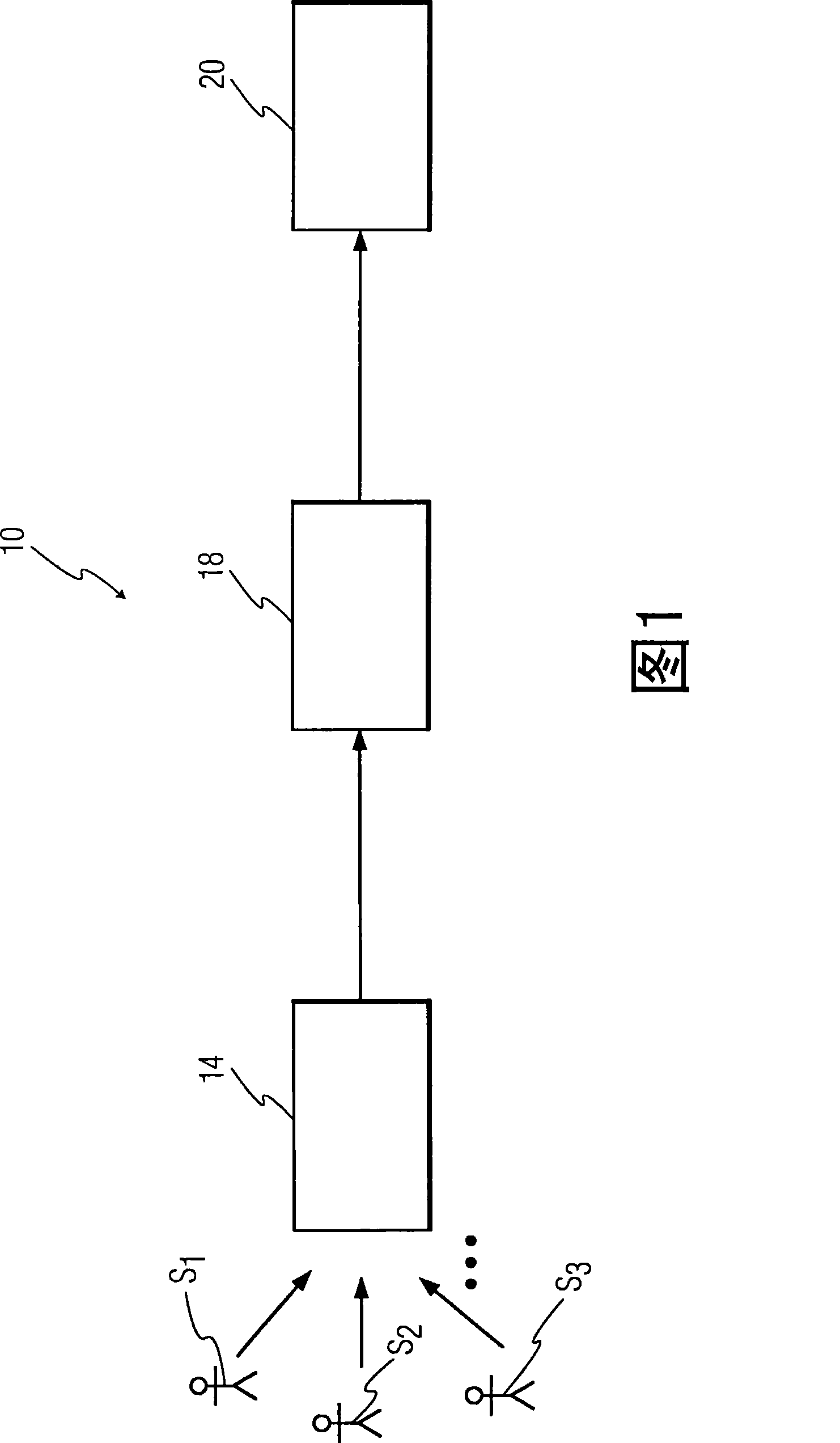
[0016] [016] The basic components of a voice-controlled ultrasound imaging system 10 according to an example of the present invention are shown in FIG. 1 . Direction tracking microphone 14 is used to provide information from one or more sonographs S 1 , S 2 , S 3 audio signal. Audio signals from microphone 14 are applied to speech recognition system 18 . Voice recognition system 18 interprets the voice command based on the audio signal and then issues a corresponding command signal to ultrasound imaging system 20 . The ultrasound imaging system 20 then performs the operations required by the voice command.

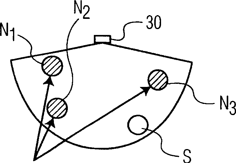
[0017] [017] Although they may not necessarily be located in the same direction relative to the system 20, it is assumed here that the sonograph S 1 , S 2 , S 3 Located within audible proximity of the ultrasound imaging system 20 . The directional microphone 14 rapidly tracks data from any sonograph S using one of several techniques described below 1 , S 2 , S 3...


PUM


Abstract

An ultrasound imaging system includes a direction- tracking microphone that is able to determine the direction of a voice command and to cause the microphone to selectively receive acoustic inputs from the determined direction. A voice recognition then interprets the voice command and controls the operation of the ultrasound imaging system accordingly. The direction tracking microphone may, for example, select one of several unidirectional microphones that receives the loudest signal or a phased array of omnidirectional microphones.

Description

field of invention [0001] [001] The present invention relates to operator control of ultrasound imaging systems, and more particularly to voice control of ultrasound imaging systems using a microphone remote from the operator of the system. Background technique [0002] [002] In recent years, the development of voice recognition technology has advanced to the point where hands-free control of ultrasound systems becomes effective when users control their ultrasound systems audibly. Several ultrasound system manufacturers, including the assignee of this application, have developed and demonstrated prototype voice-controlled ultrasound systems. One such system is described in US Patent No. 5,544,654, which is hereby incorporated by reference. In the system described in US Patent No. 5,544,654, a microphone is connected to a personal computer which interprets voice commands and sends corresponding command signals to the ultrasound system. While the microphone shown in this app...

Claims


Application Information

Patent Timeline
IPC IPC(8): G01S15/89G10L15/00G10L21/0272
CPCG01S7/52084G01S15/899A61B8/467G10L15/265G10L15/26A61B8/461A61B8/00
Inventor R·特拉姆斯
Owner KONINKLIJKE PHILIPS ELECTRONICS NV
Why Eureka
Try Eureka