

Antenna structure and electronic device
- Summary
- Abstract
- Description
- Claims
- Application Information
AI Technical Summary
Benefits of technology
Problems solved by technology
Method used
Image

Examples
Embodiment Construction
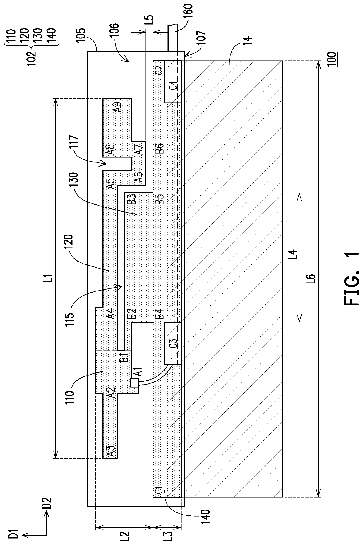
[0046]FIG. 1 is a schematic view of an antenna structure according to an embodiment of the disclosure. Referring to FIG. 1, an antenna structure 100 of the embodiment includes a first radiator 110, a second radiator 120, an antenna ground 140, and a conductor 130. Specifically, the first radiator 110 is approximately at positions A3, A2, A1, and B1; the second radiator 120 is connected to the first radiator 110 and is approximately at positions B1, A4, A5, A6, A7, A8, and A9; the conductor 130 is approximately at positions B1, B2, B3, B5, and B4; and the antenna ground 140 is approximately at position C1 to position C2.
[0047]In the embodiment, the antenna structure 100 at a feeding end (the position A1) of the first radiator 110 extends leftward to the positions A2 and A3 and rightward to the positions A4, A5, A6, A7, A8, and A9 in two respective radiation paths. The two radiation paths and ground paths of the positions B1, B2, B3, B4, and B5 form PIFA antenna architecture and reson...
PUM
 Abstract
Description
Claims
Application Information