Dynamic coherent integration

a dynamic coherent and integrated technology, applied in the field of radio signal location determination, can solve the problems of poor efficiency of gnss antennas, strict power consumption requirements, and difficulty in acquiring and tracking gnss signals for mobile devices, and achieve the effect of increasing the signal-to-noise ratio and antenna gain

Active Publication Date: 2017-03-30
APPLE INC
View PDF14 Cites 8 Cited by
  • Summary
  • Abstract
  • Description
  • Claims
  • Application Information

AI Technical Summary

Benefits of technology

[0004]Techniques for determining extended coherent integration intervals based on information about user activity, dynamics and clock stability are described. The extended coherent integration intervals may vary according to the information. Dynamically extending the coherent integration interval increases the signal-to-noise ratio during signal acquisition and tracking, thereby providing a benefit when antenna gain is poor, in weak signal conditions, and when being jammed or experiencing interference, or when power needs to be conserved, compared to extending the coherent integration interval for a fixed amount of time.
[0005]The features described in this specification can achieve one or more advantages. For example, a mobile device implementing the dynamic coherent integration techniques can compensate for interference that user-caused acceleration may have on location determination. The techniques can provide for degradation in SNR by less than 1 dB for constant acceleration up to two g's (19.6 m / s2) for up to one second of coherent integration during pedestrian motion, even when the device is handheld or worn on the wrist. A mobile device implementing the dynamic coherent integration techniques can accommodate variances in an oscillator due to oscillator construction or aging and reduce location errors caused by the varying oscillator output. A mobile device implementing the dynamic coherent integration techniques can save power without sacrificing location accuracy by adjusting coherent integration time based on priorities of power conservation.

Problems solved by technology

Acquiring and tracking GNSS signals may be challenging for mobile devices.
Mobile devices (e.g., smart phones or wearable devices) sometimes are equipped with poor-efficiency GNSS antennas, carried to harsh signal environments (e.g., indoor areas or “urban canyons” surround by signal-blocking high-rise buildings), experience jamming, and tend to have strict power consumption requirements.
The first three factors as described above, including inefficient antennas, harsh environments, and jamming, may lower a signal's carrier-to-noise density at the output of the antenna feed.

Method used


Image

  • Dynamic coherent integration
  • Dynamic coherent integration
  • Dynamic coherent integration

Examples


Embodiment Construction

GNSS Receiver Architecture

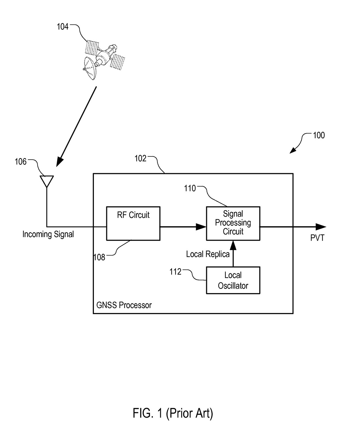
[0016]FIG. 1 is a block diagram illustrating an example conventional GNSS receiver system 100. GNSS receiver system 100 can include GNSS processor 102. GNSS processor 102 can be a processor configured to determine a geographic location from signals received from GNSS satellites 104. GNSS processor 102 can include, or be coupled to, antenna 106. Antenna 106 can be configured to receive radio frequency (RF) signals from GNSS satellites 104, and feed the received RF signals to RF circuit 108. RF circuit 108 can include circuit for preprocessing RF signals. For example, RF circuit 108 can include a low-noise amplifier (LNA) for amplifying the RF signals from antenna 106 and provide the amplified signals to signal processing circuit 110.

[0017]Signal processing circuit 110 can include analog and digital components. For example, signal processing circuit 110 can include down converter configured to convert the RF signals to intermediate frequency (IF) signals, an ...


PUM


Abstract

Systems, methods and computer program products for determining extended coherent integration intervals based on information about user activity, dynamics and clock stability. Dynamically extending the coherent integration interval increases the signal-to-noise ratio during signal acquisition and tracking, thereby providing a benefit when antenna gain is poor, in weak signal conditions, and when being jammed, or when power needs to be conserved, compared to extending the coherent integration interval for a fixed amount of time.

Description

TECHNICAL FIELD[0001]This disclosure relates generally to location determination using radio signals.BACKGROUND[0002]Extending coherent integration may improve global navigation satellite system (GNSS) signal acquisition and tracking sensitivity by increasing post-correlation signal-to-noise ratio (SNR). In coherent integration, also known as coherent averaging, sensitivity improvement grows more rapidly than that gained from non-coherent integration. Accordingly, coherent integration of a given duration outperforms non-coherent integration for the same duration. The coherent gain is, at least in part, a function of the input carrier-to-noise density and integration interval. Coherent integration can provide as much as 1.5-6 dB of gain in sensitivity for acquisition and tracking, and in some cases even more gain.[0003]Acquiring and tracking GNSS signals may be challenging for mobile devices. Mobile devices (e.g., smart phones or wearable devices) sometimes are equipped with poor-eff...

Claims


Application Information

Patent Timeline
Patent Type & Authority Applications(United States)
IPC IPC(8): G01S19/29G01S19/21H04W88/02
CPCG01S19/29G01S19/21H04W88/02G01S19/22G01S19/24G01S19/246G01S19/30
Inventor LEDVINA, BRENT M.MILLER, ISAAC THOMAS
Owner APPLE INC
Why Eureka
Try Eureka