Surface mounted broadband element

a broadband element and surface mount technology, applied in the field of antennas, can solve the problems of large total length of the element and the electronic circuit board, difficult to perform in a rational manufacturing process, and feed the antenna elements, so as to improve the antenna, improve the antenna, and improve the assembly process

Active Publication Date: 2020-09-22
SAAB AB
View PDF7 Cites 2 Cited by
  • Summary
  • Abstract
  • Description
  • Claims
  • Application Information

AI Technical Summary

Benefits of technology

[0010]An object of the present invention is to provide an improved antenna allowing an improved assembly process and / or increased reliability of the antenna. Another object of the present invention is to provide an antenna array comprising an improved antenna. Another object of the present invention is to provide a radar system comprising an improved antenna.
[0012]An antenna according to the invention improves the production process of said antenna, as the antenna elements are simpler, and the connection with the feed point is located at the bottom ground plane rather than inside the antenna element which would require a complicated transmission line and which could also diminish the cavity. The cavity of each element is formed within the element itself rather than between the feed point and the ground plane. This allows the elements that make up the antenna to be much more easily manufactured and assembled, as the important connections are located at the ground plane and may be readied before assembling the elements to the ground plane. Rather than the complex step of attaching a transmission line feed point at the end of the taper and the cavity of a Vivaldi or tapered notch element, the feed point is thus more simply connected at the bottom of the element. This allows the antenna, and by extension an antenna array using the same antennas, to be manufactured more easily in an automatic process saving time and effort. The improved manufacturing afforded by the invention is especially advantageous when using a tile-configuration for building the antenna or larger antenna structures. Additionally, the antenna allows the use of pick and place manufacturing which also constitutes an improvement in the manufacturing process. As the cavity is folded up into the element, the element can be made shorter than many previous antenna element / antenna designs.

Problems solved by technology

Using Vivaldi or tapered notch elements does have some drawbacks which are especially apparent when mounting a large amount in an array.
However, the total length of the element and the electronic circuit board will be quite large.
Also when combining perpendicular boards to dual polarized antenna arrays, the corners of the ground planes must be electrically connected, which is difficult to perform in a rational manufacturing process.
However, one difficulty is to feed the antenna elements, above the cavity, from a point on the circuit board surface.
It may also require very small parts and manual mounting and soldering.
Further, it may be difficult to achieve satisfactory fail rates of such antenna elements as the feed point may be very sensitive to faults.

Method used


Image

  • Surface mounted broadband element
  • Surface mounted broadband element
  • Surface mounted broadband element

Examples


Embodiment Construction

[0028]Various aspects of the invention will hereinafter be described in conjunction with the appended drawings to illustrate and not to limit the invention, wherein like designations denote like elements, and variations of the described aspects are not restricted to the specifically shown embodiment, but are applicable on other variations of the invention.

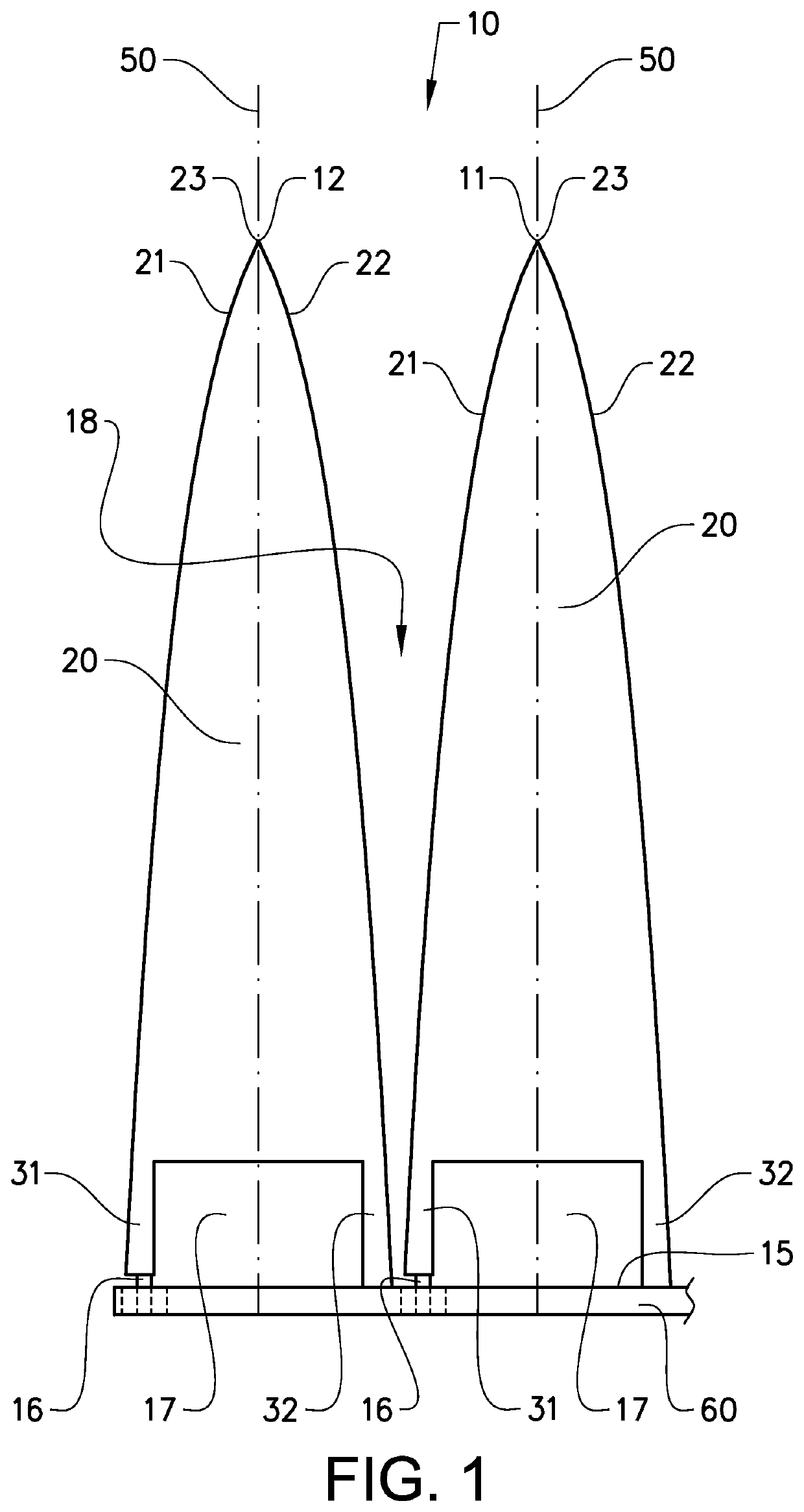
[0029]FIG. 1 shows a side view of an antenna 10 according to the invention. The antenna comprises a first antenna element 11, and a second antenna element 12. The antenna further comprises a ground plane 15 on which the first and second antenna elements 11, 12 are arranged. Each antenna element has a centre axis 50 along which each respective antenna element extend perpendicular to said ground plane. Each of the first and second antenna elements 11, 12 comprise a tip 23 located at the end of the antenna element 11, 12 located farthest away from the ground plane 15. Each antenna element 11, 12 also comprise a main body 20 and a firs...


PUM


Abstract

The disclosed subject matter concerns an antenna which comprises a ground plane and at least a first and a second antenna element. Each antenna element comprises a feed point, a cavity, a main body, a tip and at least a first tapered portion and a second tapered portion. Each antenna element is arranged on the ground plane, where said first and second tapered portions extend along the antenna element from said tip towards the ground plane of the antenna element, and where each antenna element extends essentially perpendicularly to said ground plane along a centre axis of the antenna element. Each antenna element has at least a first leg and a second leg, where said first leg extends from said main body to the first feed point, where said feed point is located between the first leg and the ground plane, and where said second leg extends from said main body to the ground plane, and where said second leg is electrically connected to the ground plane.

Description

CROSS-REFERENCES TO RELATED APPLICATIONS[0001]This application is a U.S. National Stage application of PCT / SE2014 / 051554, filed 19 Dec. 2014 and published on 23 Jun. 2016 as WO 2016 / 099367 which is hereby incorporated by reference in its entirety.TECHNICAL FIELD[0002]The present invention relates to an antenna comprising at least a first and second antenna element and a ground plane. The antenna elements comprise tapered portions which taper to a feed point near the ground plane. The invention is suitable for use in e.g. radar systems or other instances where an improved antenna may be suitable.BACKGROUND ART[0003]Antennas are used to convert electric power to and from radio waves. They are vital for use in any situation where radio waves are essential for operation such as e.g. in applications in radio, radar, cell phones, wireless networking and RFID tags.[0004]A common type of antenna element for broadband applications is a Vivaldi array antenna comprising a plurality of Vivaldi ...

Claims


Application Information

Patent Timeline
Patent Type & Authority Patents(United States)
IPC IPC(8): H01Q21/06H01Q13/08H01Q25/00H01Q1/22H01Q13/10H01Q21/00
CPCH01Q21/064H01Q21/0006H01Q1/22H01Q13/106H01Q13/085H01Q25/001
Inventor SVENSSON, BENGT
Owner SAAB AB
Why Eureka
Try Eureka