
Sensing screen, control circuit and control method thereof, and sensing screen apparatus

a technology of sensing screen and control circuit, which is applied in the direction of polarised antenna unit combination, using reradiation, instruments, etc., can solve the problems of inefficient utilization of touchscreen area of mobile terminal or portable device, size needs to be increased, and the area available for antennas becomes increasingly small, so as to increase the antenna gain, increase the antenna size, and increase the effect of antenna siz

Active Publication Date: 2017-03-30
HUAWEI TECH CO LTD
View PDF8 Cites 8 Cited by
  • Summary
  • Abstract
  • Description
  • Claims
  • Application Information

AI Technical Summary

Benefits of technology

The present application provides a sensing screen with a transparent antenna layer that allows for full utilization of the touch area without affecting the screen display. The antenna layer is placed right above the display screen, and a first antenna unit transmits a sensing signal that is reflected by second antenna units to determine the location of the touch object. This results in a cost-effective and convenient sensing function.

Problems solved by technology

However, for a mobile terminal or portable device based on high-frequency communications technologies, because a transmission loss of the high-frequency communications technologies is relatively large, in order to meet requirements of communication within a distance, an antenna size needs to be increased to increase an antenna gain.
Moreover, due to a consideration on a visual effect, if a size of the mobile terminal or portable device is limited, a size of the touch display screen of the mobile terminal or portable device becomes increasingly large, an area available for the antenna becomes increasingly small, and a touchscreen area of the mobile terminal or portable device cannot be efficiently utilized.

Method used


Image

  • Sensing screen, control circuit and control method thereof, and sensing screen apparatus
  • Sensing screen, control circuit and control method thereof, and sensing screen apparatus
  • Sensing screen, control circuit and control method thereof, and sensing screen apparatus

Examples


embodiment 1

[0036]This embodiment of the present application provides a sensing screen.

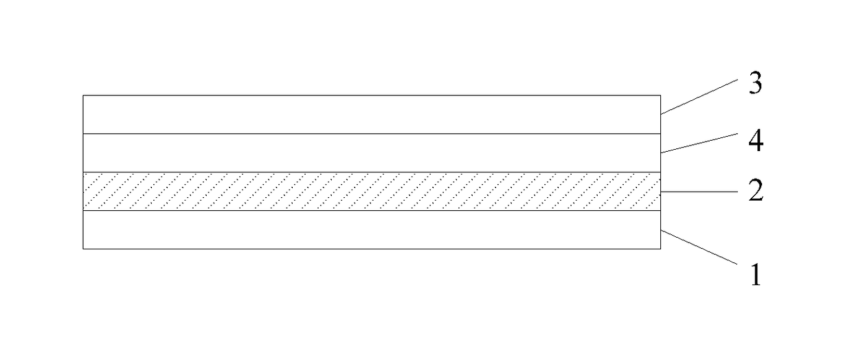
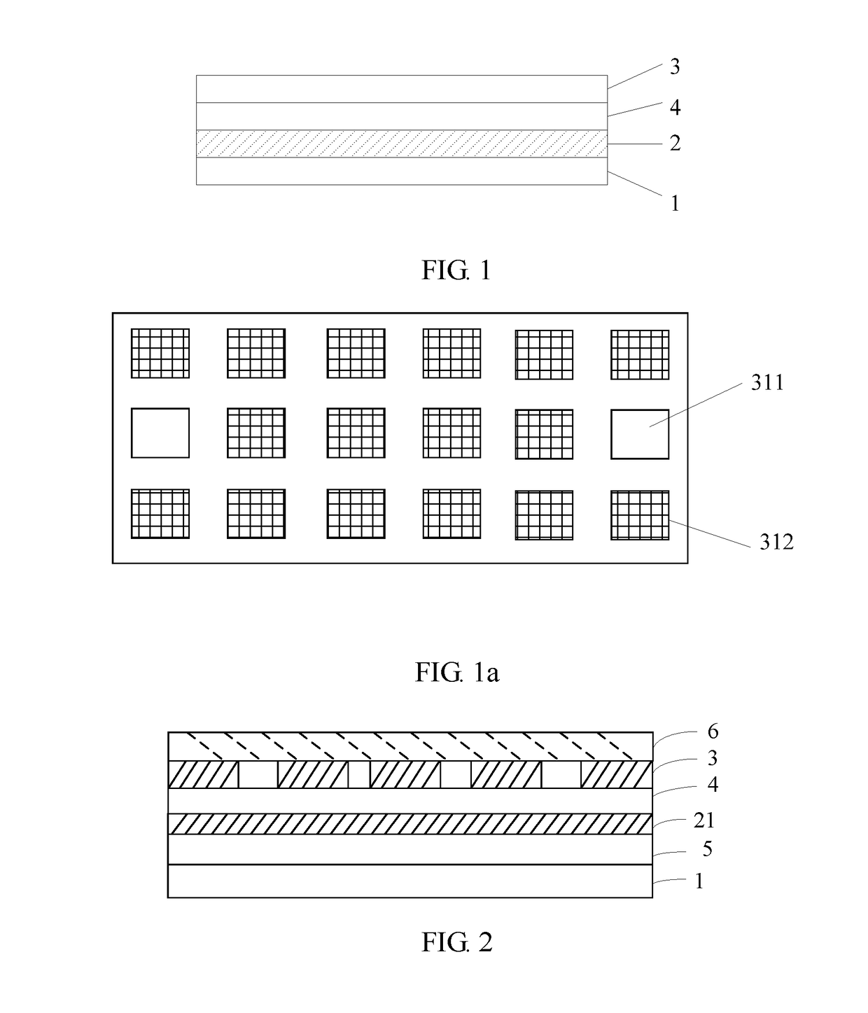
[0037]Referring to FIG. 1 and FIG. 1a, the sensing screen includes a display screen 1, a connection layer 2, a transparent antenna layer 3, and a first transparent medium layer 4. The first transparent medium layer 4 is sandwiched between the connection layer 2 and the antenna layer 3, and the connection layer 2 is sandwiched between the first transparent medium layer 4 and the display screen 1. The antenna layer 3 includes multiple antenna units 31, and the multiple antenna units 31 include at least one first antenna unit 311 and multiple second antenna units 312. An antenna of the first antenna unit 311 is configured to transmit a sensing signal, and antennas of the second antenna units 312 are configured to receive reflected signals of the sensing signal, where the reflected signals are generated by a touch object by reflecting the sensing signal. Alternatively, the first antenna unit 311 and the second an...

embodiment 2

[0040]This embodiment of the present application provides a sensing screen. Referring to FIG. 2, the sensing screen includes a display screen 1, a transparent connection layer 2, a transparent antenna layer 3, and a first transparent medium layer 4. The first transparent medium layer 4 is sandwiched between the connection layer 2 and the antenna layer 3, and the connection layer 2 is sandwiched between the first transparent medium layer 4 and the display screen 1. The antenna layer 3 includes multiple antenna units 31, and the multiple antenna units 31 include at least one first antenna unit 311 and multiple second antenna units 312. An antenna of the first antenna unit 311 is configured to transmit a sensing signal, and antennas of the second antenna units 312 are configured to receive reflected signals of the sensing signal, where the reflected signals are generated by a touch object by reflecting the sensing signal. Alternatively, the first antenna unit 311 and the second antenna...

embodiment 3

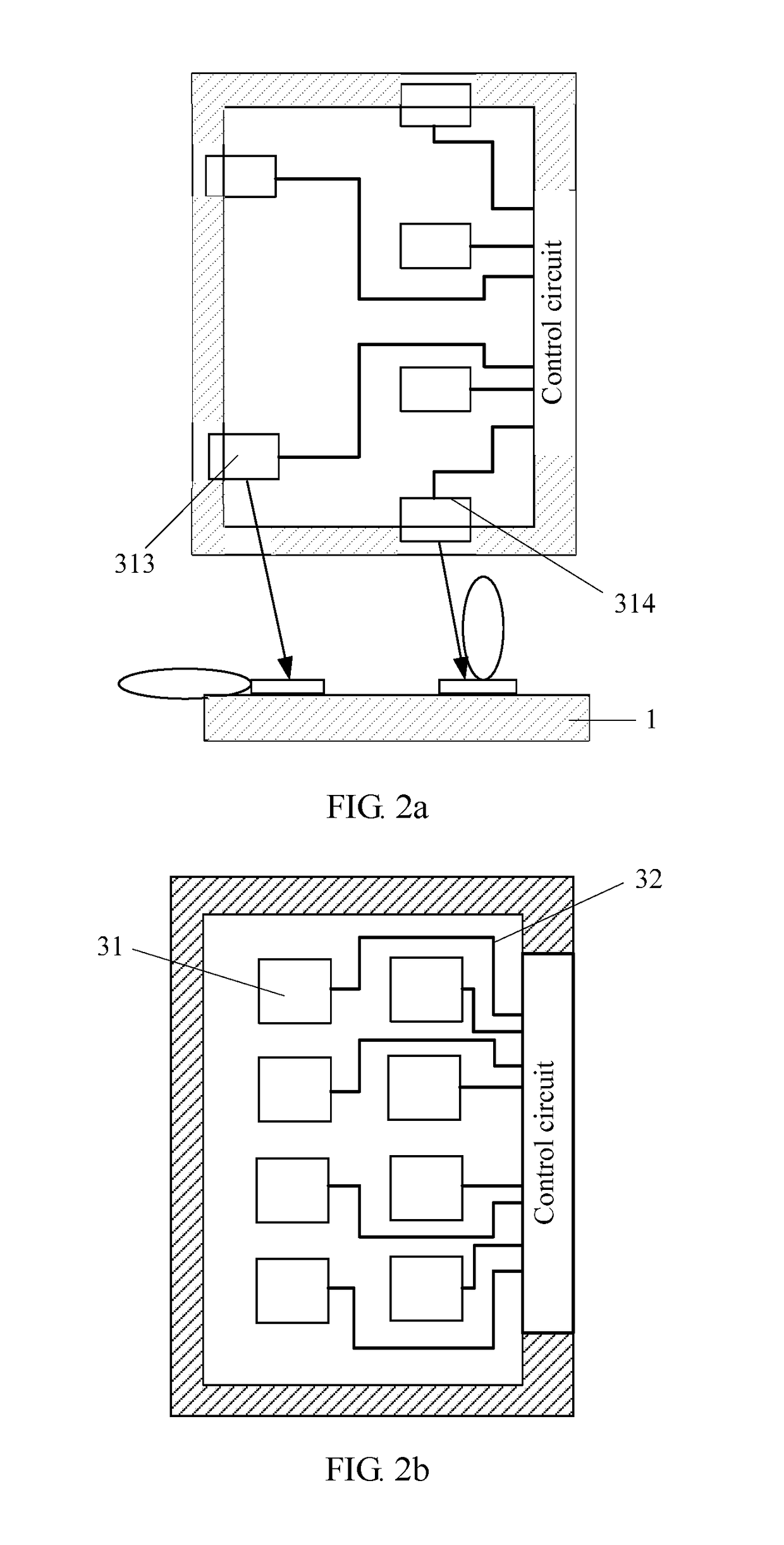
[0052]This embodiment of the present application provides a control circuit of a sensing screen. The control circuit 30 is configured to control the sensing screens corresponding to Embodiment 1 and Embodiment 2. The control circuit 30 includes an adjustment module 301 and a control module 302. The adjustment module 301 is controlled by the control module 302 to adjust a sensing signal, reflected signals, and a communication signal. The control module 302 is further configured to determine a location of a touch object according to the adjusted sensing signal and reflected signals. The adjustment module 301 is electrically connected to the sensing screen 10 and the control module 302 separately.

[0053]According to this embodiment of the present application, an antenna layer made of a transparent material, a transparent connection layer, a first transparent medium layer, and a display screen are used to make a sensing screen, and the antenna layer is arranged right above the display sc...


PUM


Abstract

The present application discloses a sensing screen, a control circuit and control method thereof, and a sensing screen apparatus. The sensing screen includes a display screen, a first transparent medium layer, a transparent connection layer, and an antenna layer. The antenna layer includes multiple antenna units, and the antenna units include at least one first antenna unit and multiple second antenna units. The first antenna unit is configured to transmit a sensing signal, the second antenna units are configured to receive reflected signals of the sensing signal, and the reflected signals are generated by a touch object by reflecting the sensing signal. According to the present application, the antenna layer is arranged right above the display screen, so that a touch area of the sensing screen is fully utilized while screen display is not affected, so as to substantially increase an antenna size and increase an antenna gain.

Description

CROSS-REFERENCE TO RELATED APPLICATIONS[0001]This application is a continuation of International Application No. PCT / CN2014 / 079647, filed on Jun. 11, 2014, the disclosure of which is hereby incorporated by reference in its entirety.TECHNICAL FIELD[0002]The present application relates to the field of wireless communications, and in particular, to a sensing screen, a control circuit and control method thereof, and a sensing screen apparatus.BACKGROUND[0003]With the development of wireless communications technologies, emerging application scenarios and demands constantly come into being in large numbers, and radio access networks also develop towards large capacities, millimeter waves, multiple bands, and the like. An antenna of a conventional mobile terminal or portable device based on low-frequency communications technologies can implement omnidirectional coverage, and a gain of the antenna is usually about 2 dBi. However, for a mobile terminal or portable device based on high-freque...

Claims


Application Information

Patent Timeline
Patent Type & Authority Applications(United States)
IPC IPC(8): H01Q1/24H01Q3/24H01Q21/24G06F3/041H01Q1/38
CPCH01Q1/243G06F3/0416G06F2203/04107H01Q21/24H01Q3/24H01Q1/38G06F3/041H01Q1/22G06F2203/04103G06F3/04164G01S13/878G01S2013/0263
Inventor CAI, HUACAO, CHANGCHEN, JINGTAO
Owner HUAWEI TECH CO LTD
Learn More