Multi-band or wide-band antenna

a multi-band or wide-band antenna technology, applied in the direction of resonant antennas, elongated active elements, radiating element structural forms, etc., can solve the problems of increasing the cost of antenna design to reduce size, increasing the cost of antenna design today, and high dielectric constant materials, etc., to achieve economic manufacturing and reduce the size of additional antennas

Inactive Publication Date: 2006-10-12
TRANSPACIFIC TECH
View PDF14 Cites 37 Cited by
  • Summary
  • Abstract
  • Description
  • Claims
  • Application Information

AI Technical Summary

Benefits of technology

[0015] An advantage of the present invention is that it provides multiple operating bands or one wide operating band for wireless communications devices.
[0016] Another advantage of the invention is that it is suitable for use in applications where space is limited, or where compactness or minimum visibility are desired.
[0017] Another advantage of the invention is that it can be economically manufactured, using commonly available materials and manufacturing techniques.
[0018] And another advantage of the invention is that its antenna volume may flexibly incorporate simply air or a dielectric material that permits additional antenna size reduction.
[0019] These and other objects and advantages of the present invention will become clear to those skilled in the art in view of the description of the best presently known mode of carrying out the invention and the industrial applicability of the preferred embodiment as described herein and as illustrated in the figures of the drawings.

Problems solved by technology

Unfortunately, existing internal antennas are either not very compact or else trade off performance quality to achieve smaller size.
Some antenna designs today also trade off increased cost to reduce size, through the use of materials with high dielectric constants which are usually expensive.
Unfortunately, that adds to the electromagnetic energy loss incurred.
This is inefficient in many applications, and is often a sever disadvantage in applications where battery capacity is a concern.
However, a patch antenna must be about a half wavelength in size, which for most terminal applications is not suitable.
This adds weight and loss and reduces the antenna bandwidth.
Due to the antenna shape, and also being a patch type antenna, it has not the proper performance and bandwidth.
However, the performance is not adequate for many applications.
WO 2004 / 109857 by Iguchi et al. teaches a PIFA-type structure based on parasitically coupling between the directly fed radiating element and the shorted radiating element, but one that has not been able to provide a reasonable bandwidth for the proper performance.
However, due to non-optimal shapes the overall antennas sizes are big.
WO 03 / 077360 by Andersson teaches yet other variations, which has a high SAR issue, as it is not completely on one side of the ground plane.
However, this technique has not been able to overcome the bandwidth issue due to its patch-type nature.
As noted in passing above, however, this approach is not as efficient as desired due to narrow bandwidth and also increasing loss.
However, due to its non-optimum shape and its configuration of the main and parasitic top loading elements, reasonable bandwidth can not be obtained, requiring the use of discrete reactive elements in many cases, as has been indicated in the patent.

Method used


Image

  • Multi-band or wide-band antenna
  • Multi-band or wide-band antenna
  • Multi-band or wide-band antenna

Examples


Embodiment Construction

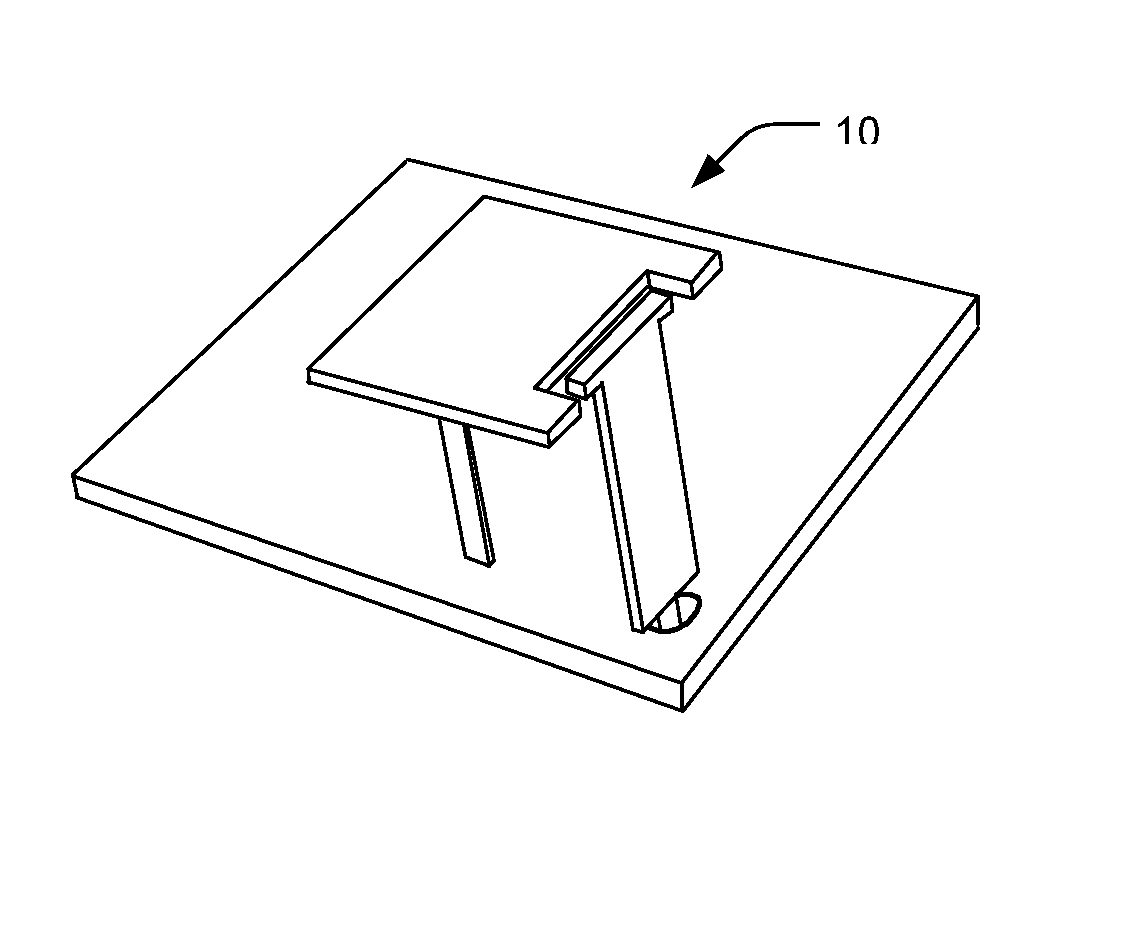
[0027] A preferred embodiment of the present invention is a multi-band antenna. As illustrated in the various drawings herein, and particularly in the view of FIGS. 1a-d, preferred embodiments of the invention are depicted by the general reference character 10.

[0028] As is common practice in this art when antennas capable of use for transmission and reception are discussed, we herein label elements and describe their roles in the context of transmission. Those skilled in the art will readily appreciate that the same elements can nonetheless also serve in reception.

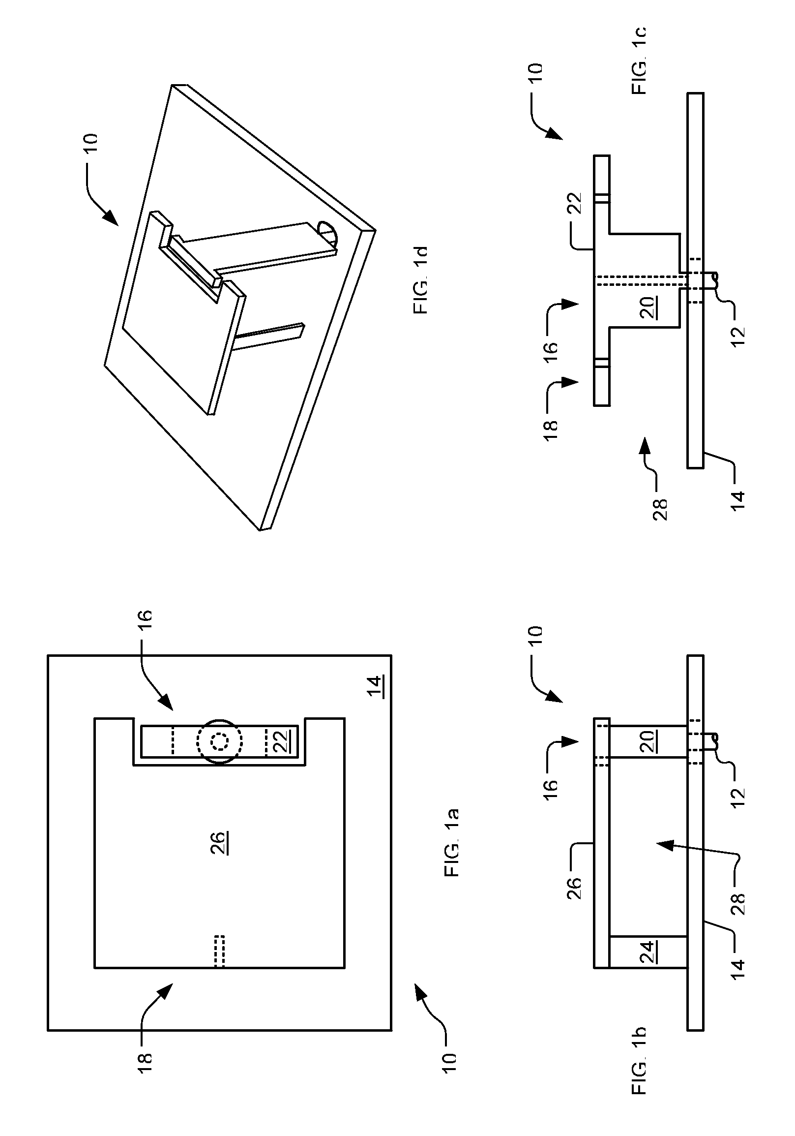
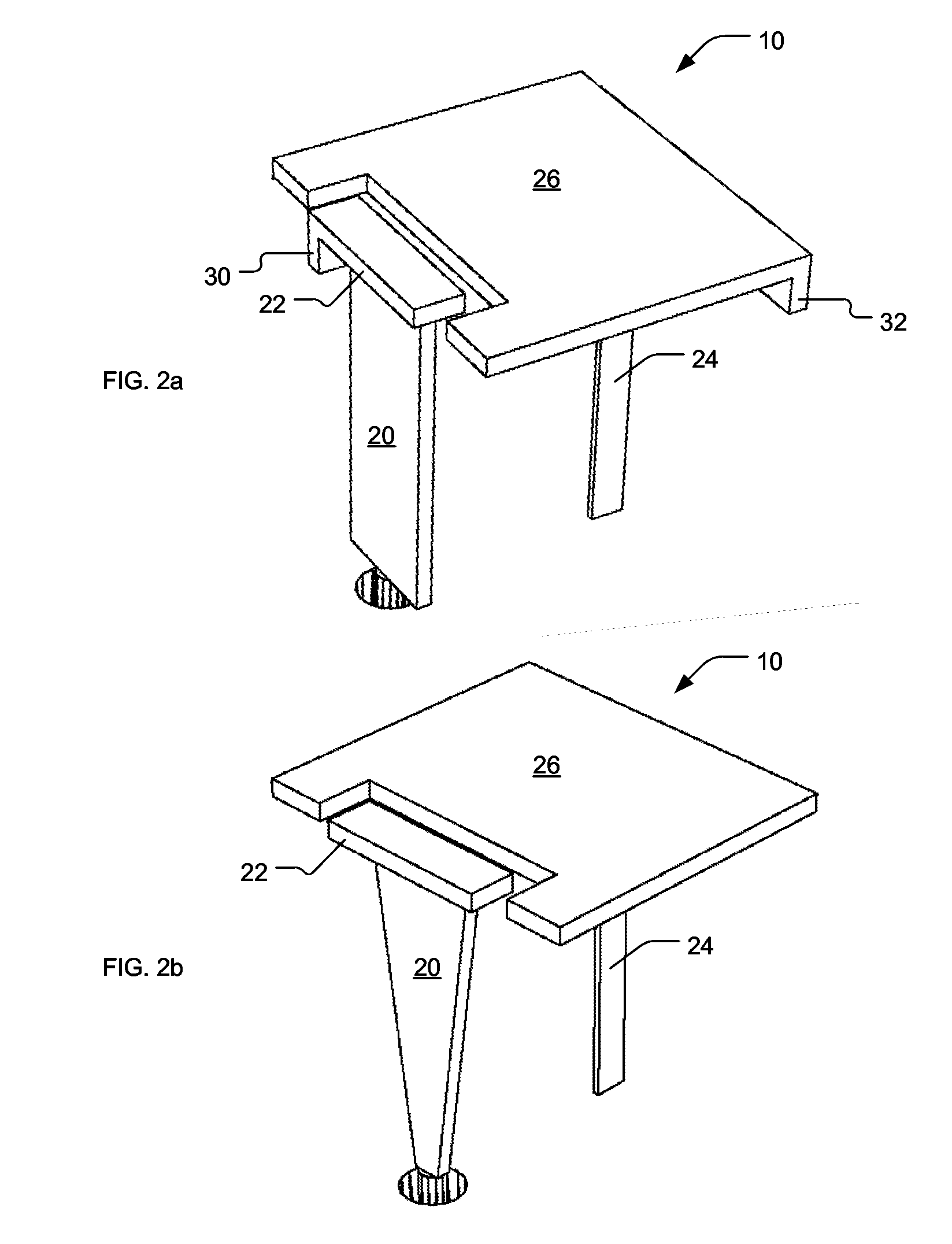
[0029]FIGS. 1a-d, respectively, depict a top plan view, a left side view, a front side view, and a perspective view of an embodiment of the inventive antenna 10 that is in accord with the present invention. The antenna 10 here includes a feed point 12, a grounding conductor or grounding surface 14, a driven radiating section 16, and a parasitic radiating section 18.

[0030] The driven radiating section 16 includes a feed ...


PUM


Abstract

A monopole-type antenna for multi- or wide-band use to transmit or receive radio frequency electromagnetic energy. A feed point, provides energy into the antenna or receives energy from the antenna. A driven radiating section includes a first top-loading element and a feed conductor that electrically connects the feed point linearly to the first top-loading element, yet with the driven radiating section not electrically connected to a grounding surface. A parasitic radiating section includes a second top-loading element and a bridge conductor that electrically connects the second top-loading element linearly to the grounding surface When energy is then provided at the feed point and conducted to the driven radiating section, it produces a first resonance mode, coupling at least some of the energy into and exciting the parasitic radiating section to produce a second resonance mode.

Description

TECHNICAL FIELD [0001] The present invention relates generally to radio wave antennas, and more particularly to such with lumped reactance at the free end for loading the antenna. It is anticipated that this invention will particularly be used with small and wireless communication devices. BACKGROUND ART [0002] Antennas for wireless communication equipment, for example pagers, cell phones and WLAN access points must be small in size, light in weight, compact in physical volume, and cheap to manufacture. Flush mounted or built-in internal antennas are therefore often desired or even required. Also, devices that communicate with wireless services often must operate in different frequency bands, due to different geographical band allocation schemes, different wireless providers, different wireless services, or different wireless communication protocols. Such devices accordingly require an antenna or multiple antennas that are responsive to multiple frequency bands. A single antenna is ...

Claims


Application Information

Patent Timeline
Patent Type & Authority Applications(United States)
IPC IPC(8): H01Q1/38H01Q5/10
CPCH01Q9/0421H01Q9/36H01Q9/0457H01Q5/50H01Q1/243
Inventor TAVASSOLI HOZOURI, BEHZAD
Owner TRANSPACIFIC TECH
Why Eureka
Try Eureka