Antenna

a technology of antennas and antennas, applied in the direction of antennas, non-resonant long antennas, antenna structural forms, etc., can solve the problems of excessive attenuation of received/transmitted signal energy and corresponding reduction of bandwidth, so as to increase antenna bandwidth, reduce antenna size, and increase antenna size

Inactive Publication Date: 2005-04-14
THALES HLDG UK
View PDF11 Cites 14 Cited by
  • Summary
  • Abstract
  • Description
  • Claims
  • Application Information

AI Technical Summary

Benefits of technology

The present invention proposes, in one of its aspects, an antenna having a tapered radiating element possessing a slow-wave structure along a tapered radiating edge thereof. The tapered radiating element supports wide bandwidths while the slow-wave structures along radiating edges extends the physical length of the radiating edge in question without increasing the size of the radiating element. This increase in radiating edge length supports an increase in antenna bandwidth without increasing antenna size, or permits one to reduce antenna size without reducing (or without significantly reducing) the bandwidth of the antenna.

Problems solved by technology

However, such solutions are generally of little effect or most likely result in undesirably excessive attenuation of received / transmitted signal energy.
However, reducing the size of an antenna has, in the prior art, typically resulted in a corresponding reduction of bandwidth.
This is undesirable.

Method used


Image

  • Antenna
  • Antenna
  • Antenna

Examples


Embodiment Construction

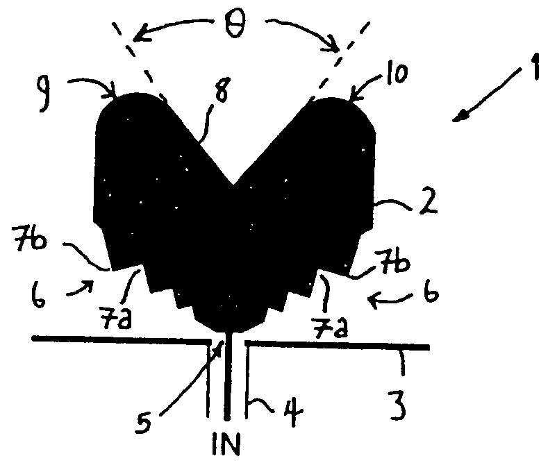
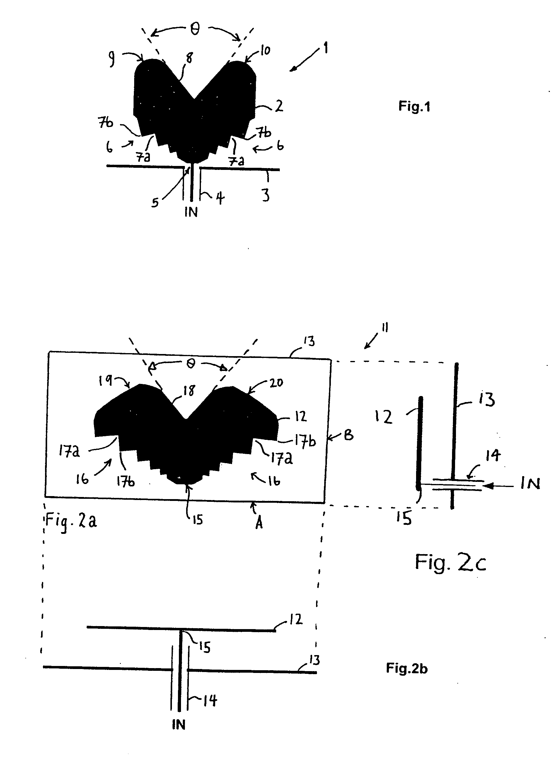
Referring to FIG. 1 there is illustrated a monopole antenna 1 comprising a planar radiating element 2 comprising a substantially flat sheet of conductive material generally shaped as a segment having two opposed slant edges 6, which diverge outwardly from an apex of the segment. The antenna radiating element 2 has a signal feed-point 5 at the apex of the segment.

The two opposed slant edges 6 diverge with increasing distance from the antenna feed-point 5 such that the radiating element 2 tapers outwardly from the feed-point. The radiating element possesses a distal peripheral edge (8, 9 and 10) which bridges the terminal outermost ends of the two opposed slant edges and forms the curved outermost periphery of the radiating element.

The radiating element has two identical series of serrations 7b each formed within a respective one of the two opposed slant edges. Each serration of a given series of serrations is formed by a pair of successive angular (tapering) notches 7a which ext...


PUM


Abstract

There is disclosed an antenna having a tapered radiating element possessing a slow-wave structure along a tapered radiating edge thereof. The radiating element is combined with a ground plane conductor to form a monopole antenna. The slow-wave structure supports an increased antenna operating bandwidth and reduced aperture clutter by being shaped to increase the radiative rate of loss of energy from signals propagating along the slow-wave structure. A log-periodic distribution in the shaping of serrations within the slow-wave structure provides substantially frequency-independent performance across the bandwidth.

Description

FIELD OF THE INVENTION The present invention relates to antennas and particularly, though not exclusively, to antennas arranged for transmitting and / or receiving brief pulses of radiation. Pulsed electromagnetic (e / m) energy transmission and reception systems typically possess wide-band or ultra wide-band (UWB) transmission spectral band widths. This UWB characteristic stems from the pulsed nature of the e / m energy transmitted or received by such systems. The shape of such energy pulses in the time-domain is typically one of any number of approximations to a delta function, and generally has the property that the width of the frequency spectrum of such impulse increases as the time-domain “length” or duration of the pulse decreases. Thus, the more brief the pulse of radiation is the broader is its spectral bandwidth. Thus, when an antenna is used employing such pulses in UWB applications, it is often found that the time-domain behaviour of the antenna is critical to the operation...

Claims


Application Information

Patent Timeline
Patent Type & Authority Applications(United States)
IPC IPC(8): H01Q1/36H01Q5/00H01Q9/04H01Q9/40H01Q19/10
CPCH01Q1/36H01Q19/106H01Q9/40H01Q9/0407H01Q5/20H01Q1/48
Inventor CHUA, LYE-WHATT
Owner THALES HLDG UK
Why Eureka
Try Eureka