System and method for implementation of a distributed data flow-based framework

Pending Publication Date: 2021-05-20
SAYANTEK INC
View PDF5 Cites 0 Cited by
  • Summary
  • Abstract
  • Description
  • Claims
  • Application Information

AI Technical Summary

Benefits of technology

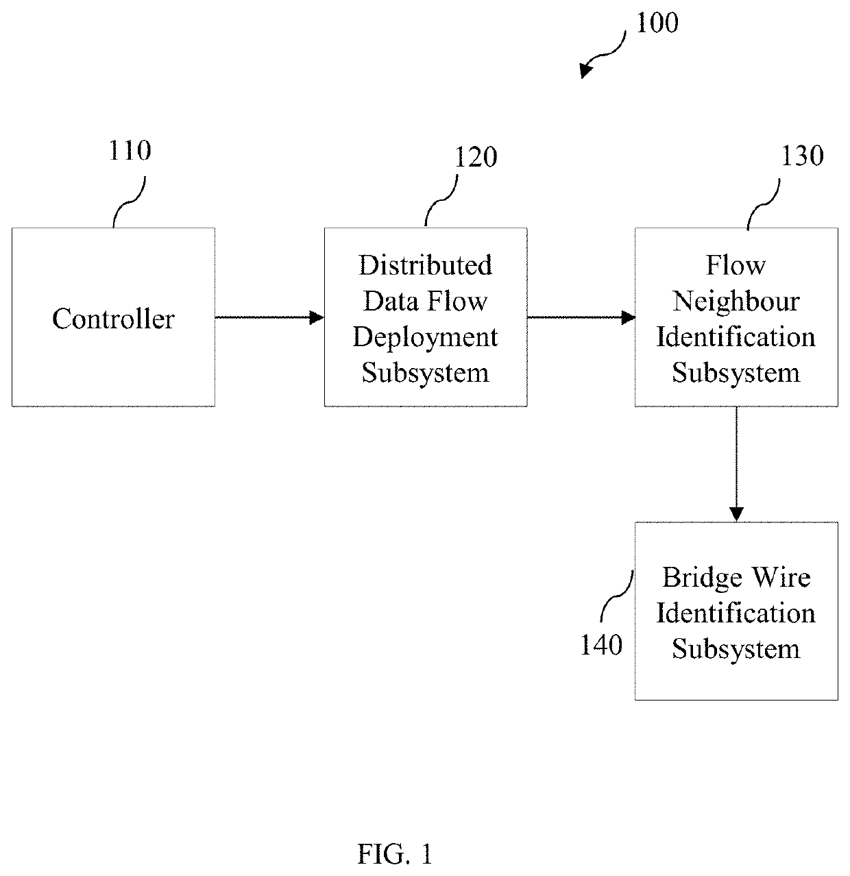
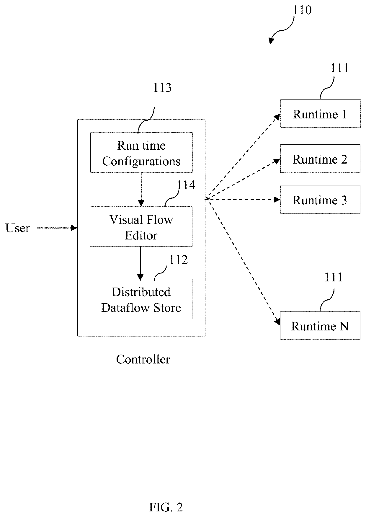
The present patent discloses a system and method for implementing a distributed data flow framework. The system includes a controller for registering runtime components of the framework and creating a flow configuration file based on the registration details. A distributed data flow deployment subsystem is then used to deploy the runtime components based on the flow configuration file. The system also includes a flow neighbor identification subsystem for identifying flow neighbors associated with the runtime components and a bridge wire identification subsystem for enabling the runtime components to establish transmission control protocol connections with the flow neighbors. The technical effects of the system and method include improved efficiency and reliability in data flow processing, better performance and scalability of distributed data processing, and improved reliability and security of data flow networks.

Problems solved by technology

Generally, the global state increases complexity and makes the system prone to instabilities due to state misuses and corruptions.
Also, every runtime is connected to the central broker and requires an involvement of the central broker for communication with other runtimes. Moreover, presence of the central broker increases latency and increases the overall system complexity.
Furthermore, the presence of the central broker limits the scalability of the data flow system and increase the total cost of ownership of such system.

Method used


Image

  • System and method for implementation of a distributed data flow-based framework
  • System and method for implementation of a distributed data flow-based framework
  • System and method for implementation of a distributed data flow-based framework

Examples


Embodiment Construction

[0019]For the purpose of promoting an understanding of the principles of the disclosure, reference will now be made to the embodiment illustrated in the figures and specific language will be used to describe them. It will nevertheless be understood that no limitation of the scope of the disclosure is thereby intended. Such alterations and further modifications in the illustrated system, and such further applications of the principles of the disclosure as would normally occur to those skilled in the art are to be construed as being within the scope of the present disclosure.

[0020]The terms “comprises”, “comprising”, or any other variations thereof, are intended to cover a non-exclusive inclusion, such that a process or method that comprises a list of steps does not include only those steps but may include other steps not expressly listed or inherent to such a process or method. Similarly, one or more devices or sub-systems or elements or structures or components preceded by “comprise...


PUM


Abstract

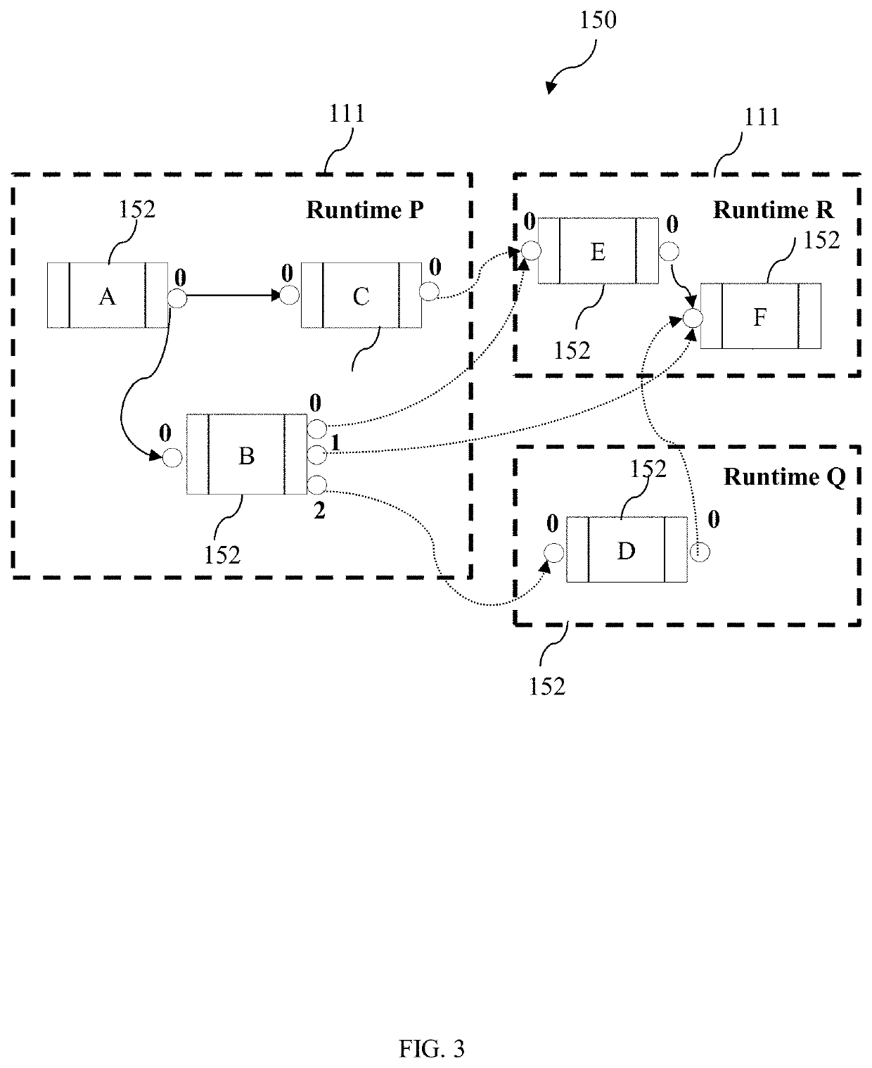
A system for implementing for implementing a distributed data flow framework. A controller creates a flow configuration file for at least one runtime. A distributed data flow deployment subsystem deploys one or more nodes and one or more interconnecting wires of the at least one runtime. A flow neighbour identification subsystem identifies one or more flow neighbours associated with the at least one runtime, determines a publisher and subscriber service information for each of the one or more flow neighbours. A bridge wire identification subsystem identifies one or more socket roles and a unique identification number corresponding to each of the one or more flow neighbours, enables the at least one runtime to establish a transmission control protocol connection with each of the one or more flow neighbours directly, implements one or more bridge wires with the at least one runtime and the one or more flow neighbours.

Description

EARLIEST PRIORITY DATE[0001]This application claims priority from a Provisional patent application filed in the United States of America having Patent Application No. 62 / 935,520, filed on Nov. 14, 2019, and titled “A METHOD OF IMPLEMENTING A DISTRIBUTED DATA FLOW SYSTEM OVER PEER-TO-PEER COMMUNICATING RUNTIMES”.BACKGROUND[0002]Embodiment of a present disclosure relates to distributed computing and automation, and more particularly to a method of implementing a distributed data flow system over peer-to-peer communicating runtimes.[0003]Dataflow programming is a design paradigm used to architect complex software systems. The data flow programming utilizes a concept of dataflow which is a directed acyclic graph (DAG) composed of ‘nodes’ and ‘wires’ that interconnects them. The nodes are asynchronous processing blocks in a system and the nodes are triggered by a message presented at its input or an event within the system. The nodes generate one or more messages which are then fed to ot...

Claims


Application Information

Patent Timeline
IPC IPC(8): H04L12/851H04L29/06H04L12/26H04L12/24H04L29/08
CPCH04L47/2483H04L69/163H04L63/02H04L41/085H04L67/1091H04L43/045H04L41/0806H04L63/061H04L47/28H04L47/2441H04L45/38H04L45/42H04L45/44H04L67/12H04L41/0883
Inventor SINGAMSETTY, MURALI KUMAR
Owner SAYANTEK INC
Why Eureka
Try Eureka