Deployment system for ruggedized illuminating, marking, or signaling device

a technology of illuminating, marking or signaling device, applied in the direction of traffic signals, roads, instruments, etc., can solve the problems of limited burn time, poor visibility, dangerous exposure of officers to passing traffic, etc., and achieve the effect of reducing the fire hazard of the vehicl

Active Publication Date: 2006-09-12
POWERFLARE CORP
View PDF25 Cites 44 Cited by
  • Summary
  • Abstract
  • Description
  • Claims
  • Application Information

AI Technical Summary

Benefits of technology

[0007]A deployment system for illumination devices, including: a holding mechanism for engaging at least one illumination device; and a deploying mechanism for causing the at least one illumination device to exit the system. The holding mechanism could be a mechanical coupling, a magnetic coupling, or a chemical adhesive. The deploying mechanism is a means of moving or allowing the movement of the illumination device with respect to the deployment system. For example, a gravity-fed door or gate release mechanism, a corkscrew mechanism, or an explosive or chemical reaction for launching the devices may be used. In the preferred embodiment, the deploying mechanism is at least one solenoid, where

Problems solved by technology

While doing so, the officer is dangerously exposed to passing traffic, compounded sometimes by poor visibility.
The use of incendiary flares poses numerous problems: they are a serious fire hazard and cannot be used in areas where dry brush or other hazardous or flamma

Method used


Image

  • Deployment system for ruggedized illuminating, marking, or signaling device
  • Deployment system for ruggedized illuminating, marking, or signaling device
  • Deployment system for ruggedized illuminating, marking, or signaling device

Examples


Embodiment Construction

[0016]The present invention provides an improved deployment system for illumination devices. The following description is presented to enable one of ordinary skill in the art to make and use the invention and is provided in the context of a patent application and its requirements. Various modifications to the preferred embodiment will be readily apparent to those skilled in the art and the generic principles herein may be applied to other embodiments. Thus, the present invention is not intended to be limited to the embodiment shown but is to be accorded the widest scope consistent with the principles and features described herein.

[0017]To more particularly describe the features of the present invention, please refer to FIGS. 1 through 8 in conjunction with the discussion below.

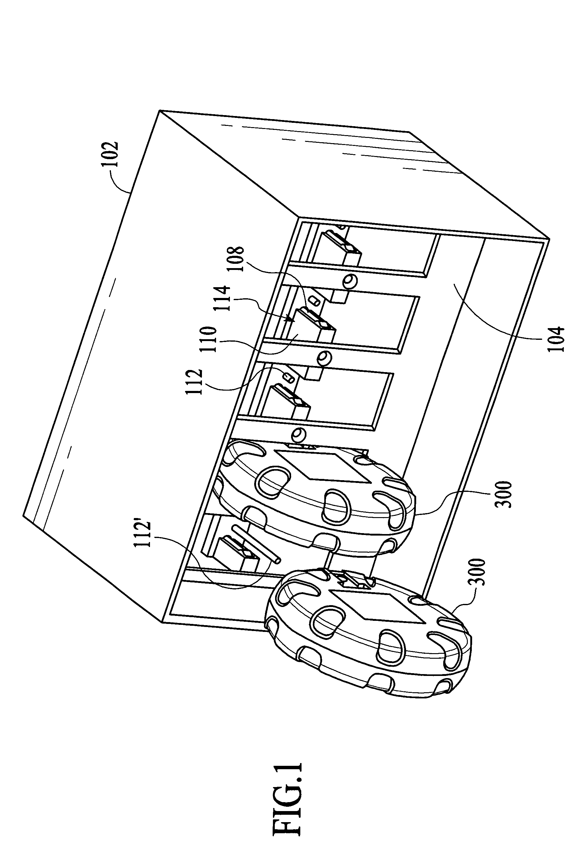
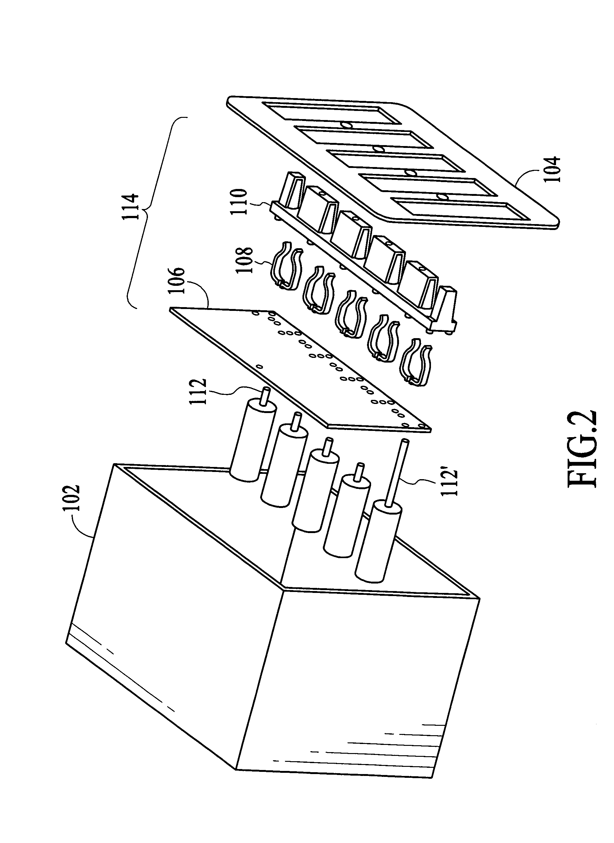
[0018]FIG. 1 illustrates a preferred embodiment of a deployment system for illumination devices in accordance with the present invention. FIG. 2 illustrates an exploded view of the deployment system in accorda...


PUM


Abstract

A deployment system for illumination devices, including: a holding mechanism for engaging at least one illumination device; and a deploying mechanism for causing the at least one illumination device to exit the system. In the preferred embodiment, the deploying mechanism is at least one solenoid, where the at least one solenoid extends to cause the illumination device to exit the system. The system allows a user or an automated system to deploy illumination devices without being exposed to dangerous conditions. For example, the system can be mounted internally or externally to a law enforcement, road crew, or utility company vehicle. The user may then deploy the illumination devices to mark the road without being subjected to the dangers of oncoming traffic.

Description

CROSS-REFERENCE TO RELATED APPLICATIONS[0001]This application claims priority from co-pending U.S. Provisional Patent Application Ser. No. 60 / 426,248, entitled “Ruggedized Electronic Traffic Safety Device and Automated Vehicle Deployment System,” filed on Nov. 13, 2002.[0002]This application is related to co-pending regular U.S. patent application Ser. No. 10,712,431, entitled “Ruggedized Illuminating, Marking, or Signaling Device,” filed on Nov. 12, 2003.FIELD OF THE INVENTION[0003]The present invention relates to deployment of electronic devices, and more particularly to the deployment of illuminating, marking, or signaling electronic devices.BACKGROUND OF THE INVENTION[0004]Emergency responders and other road workers often use incendiary flares to mark a scene of a traffic accident, road closure, or work zone. The officer must park his patrol car, open the trunk, obtain some flares, and walk back into traffic to deploy them. The officer must then light each flare and put it on th...

Claims


Application Information

Patent Timeline
IPC IPC(8): G08B23/00
CPCB60Q7/00B60Q1/52F21L2/00
Inventor DUEKER, KENNETH S.HAGELIN, PAUL M.EDWARDS, TROY J.TAVERNETTI, RUSSELL E.
Owner POWERFLARE CORP
Why Eureka
Try Eureka