
Unmanned storage system and warehouse output and input method

A warehousing system and shelf technology, applied in the field of unmanned warehousing system and inbound and outbound, can solve the problems of high cost, less reserved space, and high deployment cost, and achieve the effect of small load capacity, short implementation period, and efficient transportation

Active Publication Date: 2019-07-09
杭州大氚智能科技有限公司
View PDF5 Cites 41 Cited by
  • Summary
  • Abstract
  • Description
  • Claims
  • Application Information

AI Technical Summary

Problems solved by technology

This solution requires the installation of a three-dimensional warehouse, and the deployment cost is high. When a failure occurs inside the three-dimensional warehouse, it cannot continue to work. The mobile car can only move around the periphery of the three-dimensional warehouse and cannot enter its internal space. Increase the number of moving cars to improve throughput and efficiency
[0006] To sum up, most of the existing solutions are either complicated to deploy, requiring on-site modification and installation of a large number of auxiliary electromechanical equipment, which cannot continue to work when the equipment fails, and maintenance is inconvenient, or although no on-site modification is required, a large number of costly Heavy-duty mobile trolley or robotic arm
Complicated deployment, inconvenient maintenance, and high cost limit promotion

Method used


Image

  • Unmanned storage system and warehouse output and input method
  • Unmanned storage system and warehouse output and input method
  • Unmanned storage system and warehouse output and input method

Examples


Embodiment 1

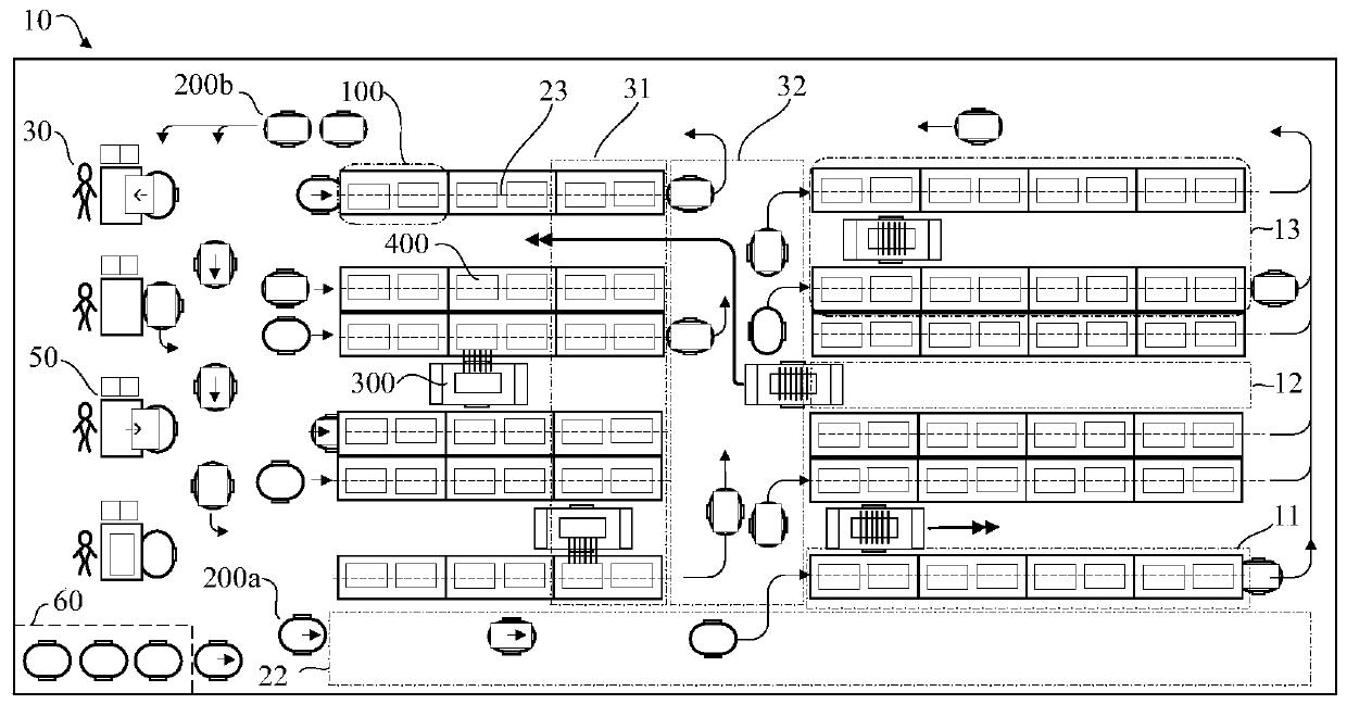
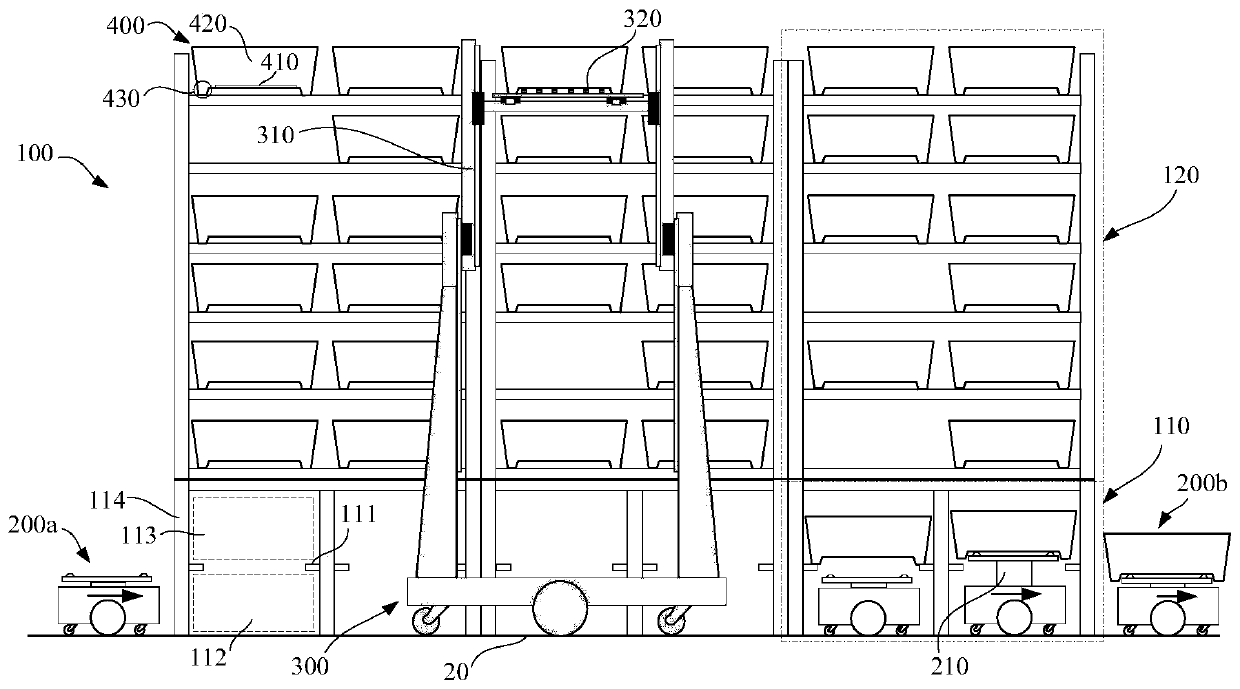
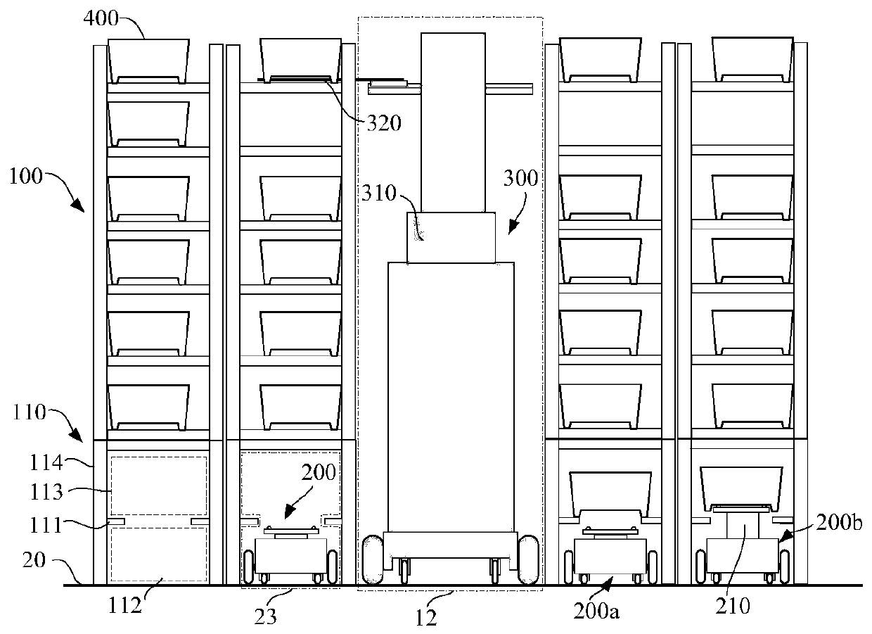
[0035] Such as figure 1 As shown, Embodiment 1 of the present invention provides an unmanned storage system based on a mobile robot and a cache space and a method for entering and exiting the warehouse, which involves a storage sorting system. The storage system 10 includes a scheduling control system, not shown in the figure, and multiple Shelves 100, multiple automatic guided vehicles 200, multiple stackers 300, and optional sorting workstations 50, etc. The AGV 200 and the stacker 300 are generally powered by built-in batteries.

[0036] Each automatic guided vehicle 200 and stacker 300 communicates with the dispatch control system through a wireless communication network. The automatic guided vehicle 200 and stacker 300 rely on their own sensors, such as laser radar, visual sensor, magnetic line reader, etc., And with the help of navigation markers arranged in the warehouse, such as reflective strips, QR codes, RFID patches, etc., automatic movement and positioning can be...

Embodiment 2

[0061] Figure 7 It is a schematic diagram of a typical fixed structural support on the channel support frame in Example 2 of the present invention. which for Figure 7 In the channel support frame shown in a, the standardized container 400 can be docked above the support and can move in the row direction and the column direction. The advantage of adopting this structure is that the path planning of the automatic guided trolley is more flexible; and for Figure 7 In the channel support frame shown in b, the standardized container 400 can be docked on the support member, but can only move along the column direction parallel to the long metal plate. The advantage of adopting this structure is that the rigidity of the channel support frame can be improved.

[0062] Figure 8 It is a schematic diagram of the overall layout of the item sorting system in Embodiment 2 of the present invention and the schematic diagram of the principle when the automatic guided trolley runs along th...

Embodiment 3

[0067] Figure 9 It is a schematic diagram of the overall layout of the item sorting system in Embodiment 3 of the present invention and the schematic diagram of the principle when the automatic guided trolley runs along the row direction in the dedicated row aisle for the trolley, and runs along the column direction under the shelves. This embodiment generally adopts the same as embodiment 2 such as Figure 7 Fixed structural supports shown.

[0068] The difference from Embodiment 2 is that in this embodiment, several lanes 21 dedicated to trolleys are added between two sets of rack lane combinations 13 . Figure 8 Taking the addition of a laneway 21 dedicated to trolleys as an example, the automatic guided trolleys 200 enter the laneway from one end in sequence, and after reaching the designated rack row, turn in situ, and then enter the corresponding laneway 33 . The counterclockwise arrows and clockwise arrows on some of the dollies in the figure indicate that the dolly ...


PUM


Abstract

The invention discloses an unmanned storage system and a warehouse output and input method. The problems that an existing system is complex in deployment, inconvenient to maintain, high in cost and the like are solved. In the embodiment of the invention of the system, two-layered channel supporting frames are arranged below storage racks, lower layers are used for allowing automatic guided vehicles to pass, upper layers are used for allowing normalized containers to be temporally cached or pass through, and interlayer supporting plates are through in the length direction or width directions ofthe whole storage racks. During implementation of goods warehouse output, forklift trucks move to the specified storage racks automatically and align the corresponding storage racks, the normalized containers on the storage racks are taken out with a goods collecting mechanism, then the forklift trucks descend to the upper layers of the supporting frames, and the containers are cached on the supporting plates; afterwards, the automatic guided vehicles move to the lower sides of the containers via the lower layers of the supporting frames to jack up the containers and further be disengaged from supporting pieces; and then the vehicles move to sorting sites via channels and roadways, and the warehouse input process is just on the contrary. The system can be deployed easily and is easy to maintain and low in cost, a large quantity of robots can execute concurrent operations through a scheduling system and the overall efficiency is high.

Description

technical field [0001] The invention relates to the technical field of warehousing, in particular to an unmanned warehousing system and a method for entering and leaving the warehouse. Background technique [0002] The core issue of automated warehousing is the efficient and automated transportation of items between shelves and sorting workstations. At present, many warehouses have begun to implement automation, equipped with a large number of mechanical equipment, such as integrated shelves, shuttle cars, stackers, forklifts, automatic guided vehicles or AGV, conveyor belts, etc., which reduces labor costs and improves storage and sorting efficiency. But these schemes also have unsatisfactory aspects. [0003] Compared with solutions such as integrated shelves and shuttle vehicles, the automated storage solution using mobile robots requires less on-site modification, and is easier to deploy and achieve high concurrent operations, so it is more popular in some occasions. A...

Claims


Application Information

Patent Timeline
Patent Type & Authority Applications(China)
IPC IPC(8): B65G1/04
CPCB65G1/0492B65G1/0407
Inventor 赵悦荣刘美艳
Owner 杭州大氚智能科技有限公司
Learn More