Working machine support belt

a technology for supporting belts and working machines, applied in the field of supporting belts for working machines, can solve the problems of difficulty in applying a load to the chest of users, and achieve the effects of reducing fatigue due to a local load on the body of the operator, reducing the deviation of the load that acts on the waist, and reducing the fatigue of the operator's body

Active Publication Date: 2021-06-03
HONDA MOTOR CO LTD
View PDF0 Cites 0 Cited by
  • Summary
  • Abstract
  • Description
  • Claims
  • Application Information

AI Technical Summary

Benefits of technology

[0008]According to the working machine support belt of the present invention, the load on the working machine can be more effectively distributed to the upper body compared to the related art. In addition, since the load on the working machine can be distributed around the entire waist of the operator, the deviation of the load that acts on a waist can be reduced, and fatigue due to a local load on the body of the operator can be reduced.

Problems solved by technology

According to the working machine support belt of Patent Document 1, the free front end portion of the shoulder belt is positioned to be apart from the front end portions of each of the pelvis belt and the side belt, and thus, it is difficult to apply a load to the chest of the user.

Method used


Image

  • Working machine support belt
  • Working machine support belt
  • Working machine support belt

Examples


Embodiment Construction

[0016]Hereinafter, an embodiment of the present invention will be described with reference to the attached drawings.

[Entire Configuration of Working Machine Support Belt]

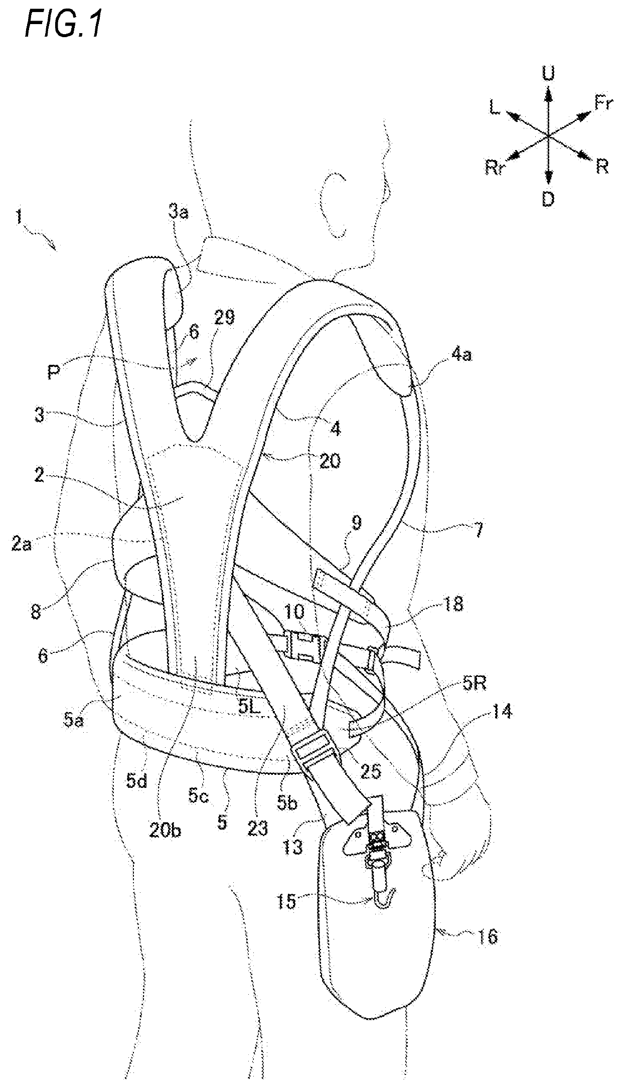
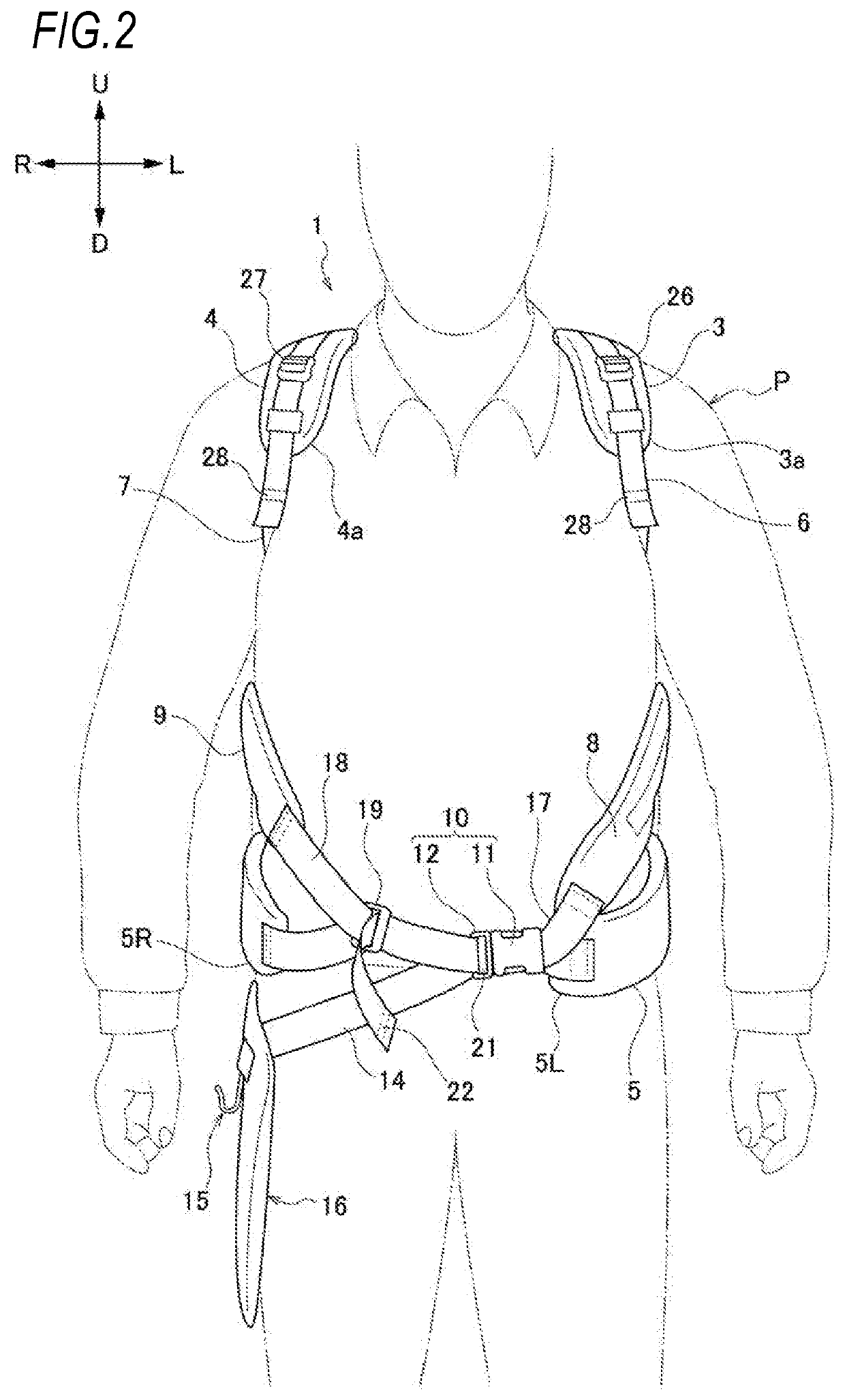
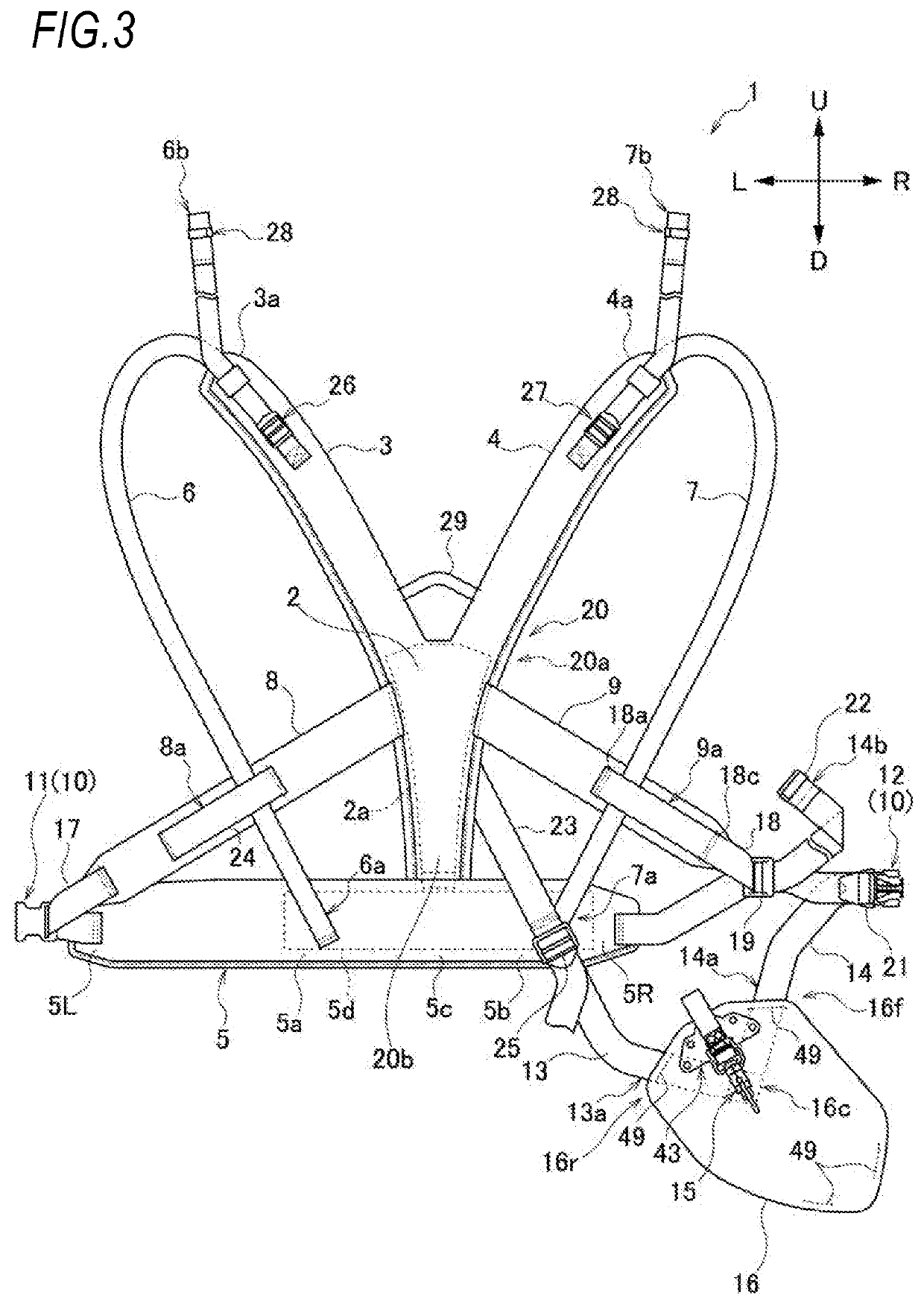
[0017]As illustrated in FIGS. 1 to 3, a working machine support belt 1 of the embodiment includes: a back plate portion 2; a left shoulder belt 3 and a right shoulder belt 4 that extend upward from an upper portion of the back plate portion 2 and turn to a front part of an operator P; a waist belt 5 that extends from a lower portion of the back plate portion 2 to both sides; a left suspender band 6 that connects a front lower portion 3a of the left shoulder belt 3 and a left rear portion 5a of the waist belt 5; a right suspender band 7 that connects a front lower portion 4a of the right shoulder belt 4 and the right rear portion 5b of the waist belt 5; a left side belt 8 that extends left-downward from the upper portion of the back plate portion 2, turns to the front part of the operator P, and is connected to a lef...


PUM


Abstract

A working machine support belt includes: a back plate portion; a left shoulder belt and a right shoulder belt; a waist belt; a left suspender band that connects the left shoulder belt and the waist belt; a right suspender band that connects the right shoulder belt and the waist belt; a left side belt that extends left-downward from the back plate portion, turns forward, and is connected to a left end portion of the waist belt; a right side belt that extends right-downward from the upper portion of the back plate portion, turns forward, and is connected to a right end portion of the waist belt; a locking member that locks the left end portion and the right end portion of the waist belt; and a pad member supported via a rear support band and a front support band, and provided with a hook that supports a working machine.

Description

TECHNICAL FIELD[0001]The present invention relates to a working machine support belt.BACKGROUND ART[0002]As a working machine support belt for supporting a working machine, such as a mowing machine, with an upper body of a user, there is known a technology including: a back plate; a shoulder belt fixed to the back plate and having a free front end portion; a side belt which extends forward through the left and right armpits from the back plate and of which the front end portion almost ends in a lower range of the chest of the user; a support plate on which working machinery abuts; and a pelvis belt provided below the side belt, in which the support plate is connected to the back plate and the side belt via a support band, and the free front end portion of the shoulder belt is disposed to be apart from the front end portions of each of the pelvis belt and the side belt (Patent Document 1).[0003]According to the working machine support belt of Patent Document 1, the free front end por...

Claims


Application Information

Patent Timeline
Patent Type & Authority Applications(United States)
IPC IPC(8): A45F3/14A01D34/90
CPCA45F3/14A01D34/90A45F2003/146A45F2003/142A45F2003/144
Inventor HASEGAWA, TETSUYA
Owner HONDA MOTOR CO LTD
Why Eureka
Try Eureka