Touch switch

Active Publication Date: 2021-06-03
CHEN YU TA
View PDF0 Cites 0 Cited by
  • Summary
  • Abstract
  • Description
  • Claims
  • Application Information

AI Technical Summary

Benefits of technology

[0004]The primary object of the present invention is

Problems solved by technology

As to the above-mentioned conventional electrical switch, due to the frequent use of the push switch or the togg

Method used


Image

  • Touch switch
  • Touch switch
  • Touch switch

Examples


Example

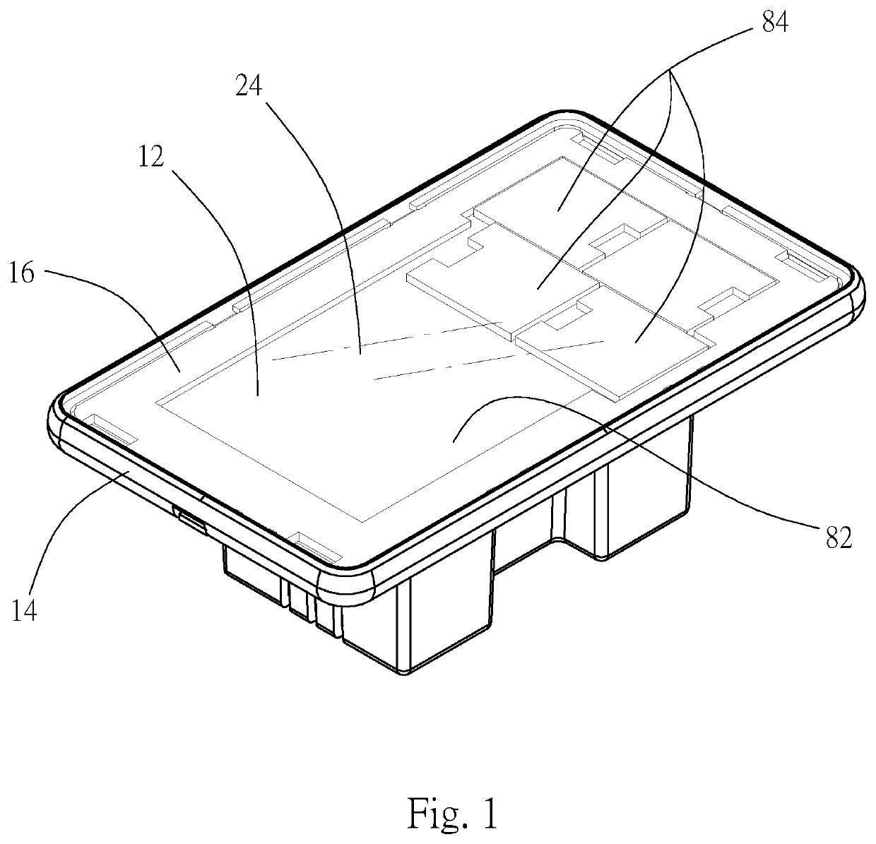
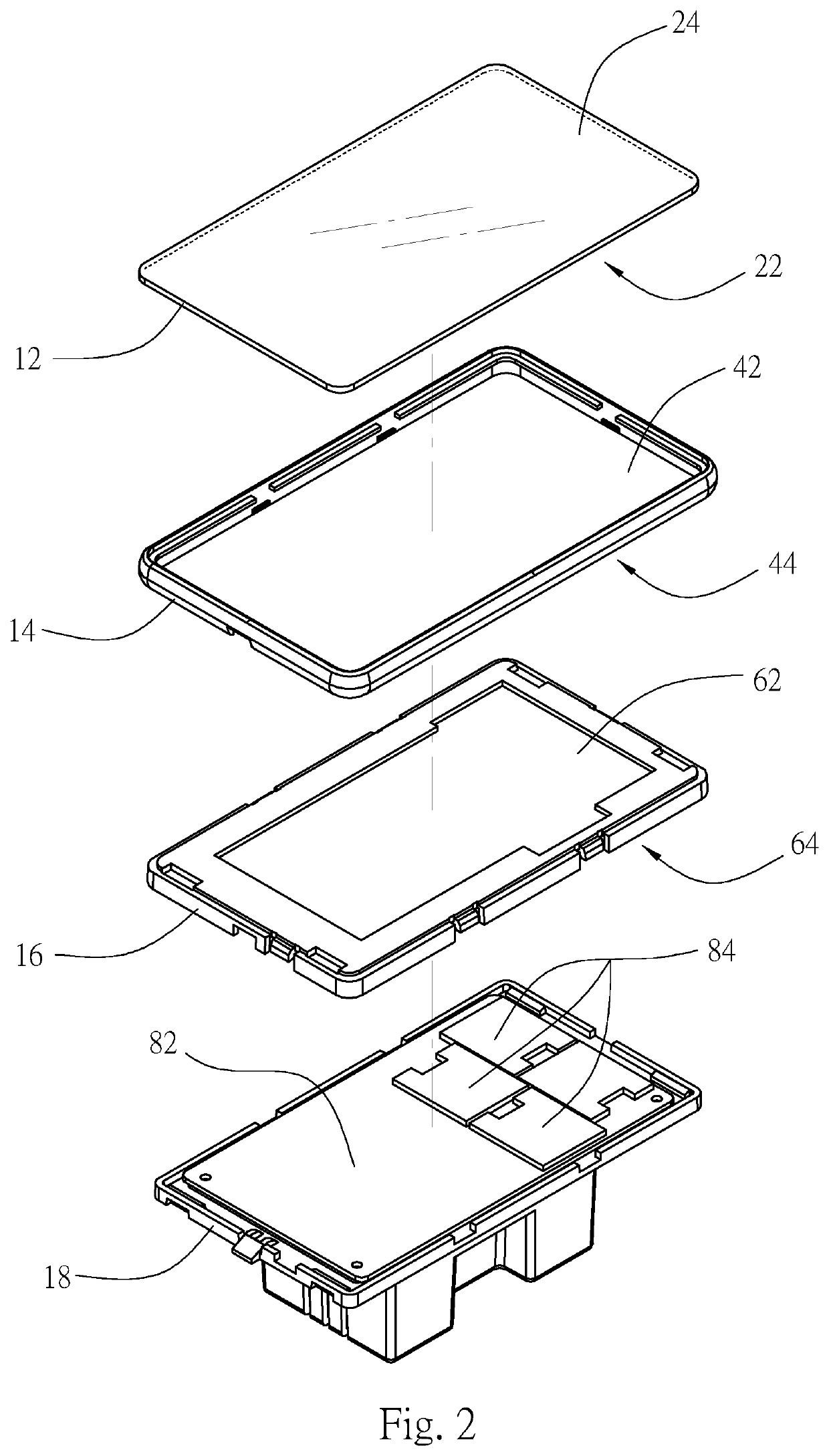
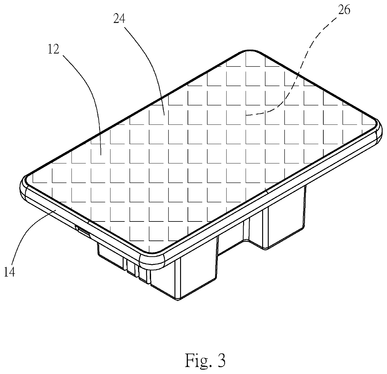
[0013]Referring to FIG. 1 and FIG. 2, a touch switch of the present invention comprises a light-pervious plate 12, a first peripheral frame 14, a second peripheral frame 16 and an electrical switch module 18 that are arranged in sequence.

[0014]The light-pervious plate 12 has a predetermined shape, such as a rectangular shape with four curved corners, a polygonal shape, or a circular shape (not shown). The light-pervious plate 12 may be made of a glass material.

[0015]The first peripheral frame 14 may be made of a metal aluminum material. In this embodiment, the inner edge of the first peripheral frame 14 corresponds in shape to the outer edge of the light-pervious plate 12. The periphery of one side face 42 of the first peripheral frame 14 is glued or inlayed to the periphery of one side face 22 of the light-pervious plate 12.

[0016]The second peripheral frame 16 may be made of a thermoplastic polymer material, such as Acrylonitrile Butadiene Styrene (ABS). In this embodiment, the out...


PUM


Abstract

A touch switch includes a light-pervious plate, a first peripheral frame, a second peripheral frame and an electrical switch module. The light-pervious plate has a predetermined shape. The first peripheral frame corresponds in shape to the light-pervious plate. One side face of the first peripheral frame is coupled to one side face of the light-pervious plate. The second peripheral frame corresponds in shape to of the first peripheral frame. One side face of the second peripheral frame is coupled to another side face of the first peripheral frame. The electrical switch module corresponds in shape to the second peripheral frame. One side face of the electrical switch module is coupled to another side face of the second peripheral frame. The side face of the electrical switch module is provided with at least one light sensitive switch.

Description

FIELD OF THE INVENTION[0001]The present invention relates to an electrical switch, and more particularly to a touch switch.BACKGROUND OF THE INVENTION[0002]Generally, a wall-mounted electrical switch includes a base and a panel. The base is coupled to an opening of the wall. The inner side face of the base is connected with the wires inside the wall. The outer side face of the base is provided with a push switch or a toggle switch. The panel is coupled to the outer side face of the base to shield the opening of the wall. The push switch or the toggle switch is exposed to the panel for a user to turn on or off the electrical appliance to which the base is connected.[0003]As to the above-mentioned conventional electrical switch, due to the frequent use of the push switch or the toggle switch, the circuit contacts or the positioning engaging structure may wear out and lose its switching effect. Moreover, the panel is a simple plastic panel without any decorative and visual effect.SUMMA...

Claims


Application Information

Patent Timeline
IPC IPC(8): H03K17/96
CPCH03K17/9627H03K2217/96015
Inventor CHEN, YU TA
Owner CHEN YU TA
Why Eureka
Try Eureka