

Lantern stand
- Summary
- Abstract
- Description
- Claims
- Application Information
AI Technical Summary
Benefits of technology
Problems solved by technology
Method used
Image

Examples
Embodiment Construction
[0023]Embodiments are described more fully below with reference to the accompanying figures, which form a part hereof and show, by way of illustration, specific exemplary embodiments. These embodiments are disclosed in sufficient detail to enable those skilled in the art to practice the invention. However, embodiments may be implemented in many different forms and should not be construed as being limited to the embodiments set forth herein. The following detailed description is, therefore, not to be taken in a limiting sense in that the scope of the present invention is defined only by the appended claims.
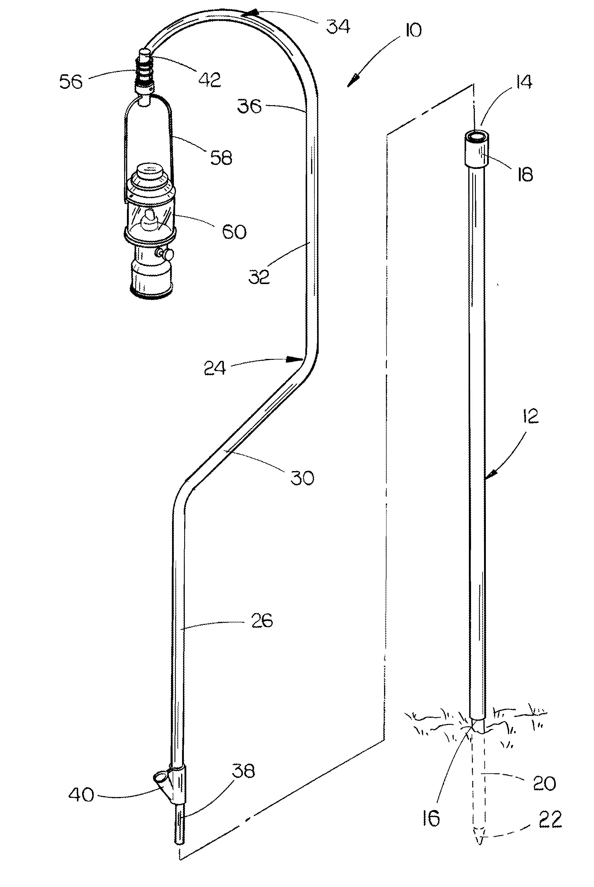
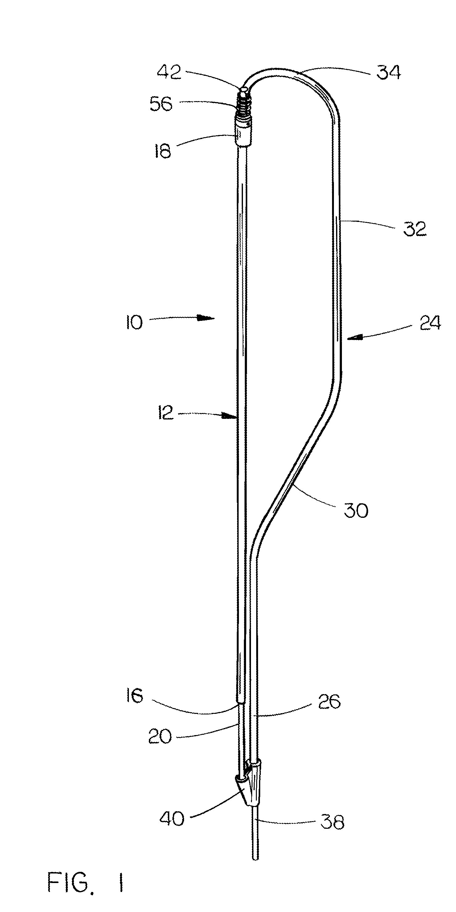
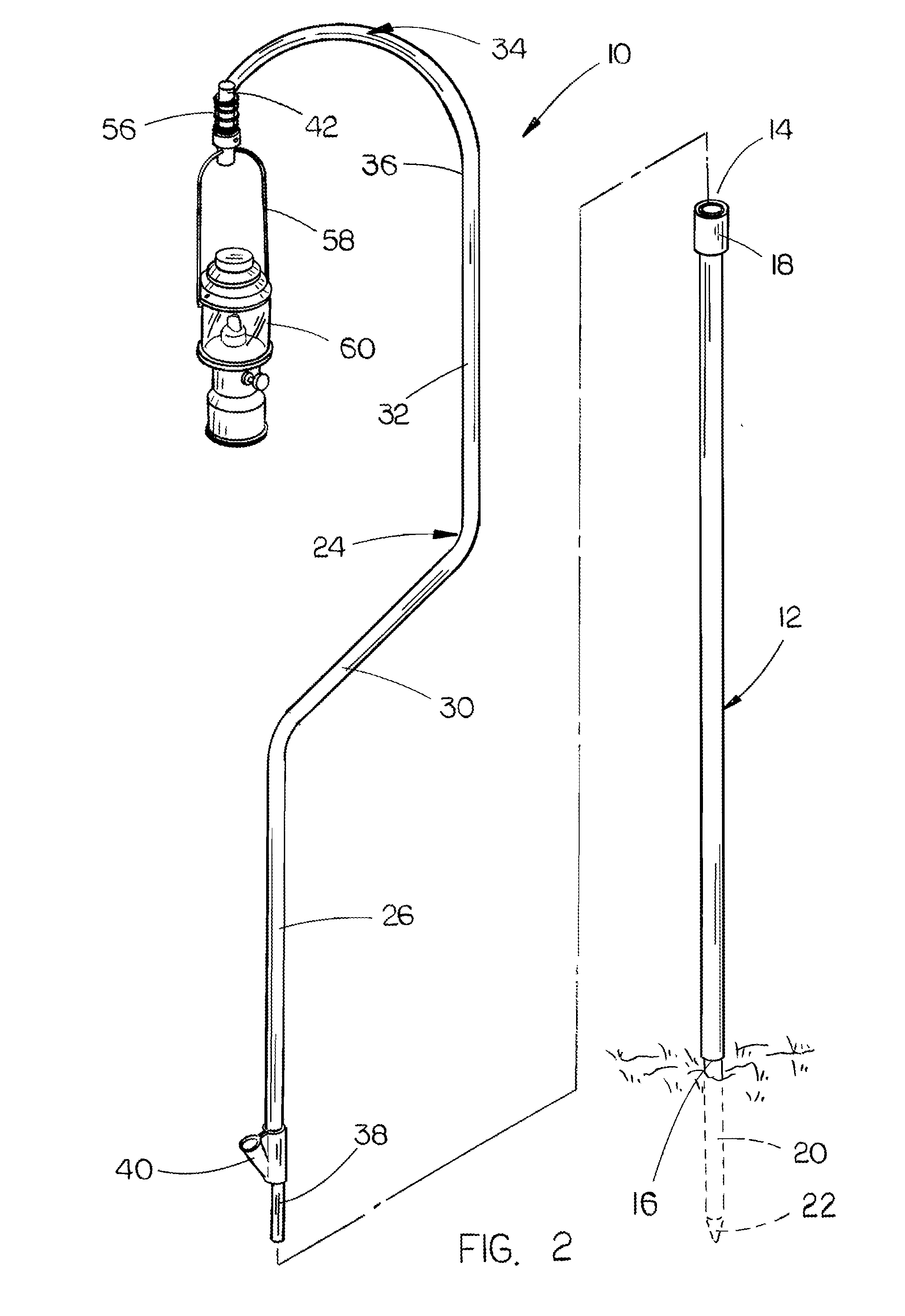
[0024]The lantern stand of this invention is referred to generally by the reference numeral 10. Stand 10 includes a hollow extension tube 12 having an upper end 14 and a lower end 16. A hollow collar 18 is secured to the upper end 14 of tube 12 so as to embrace the same. A spike 20 is secured to the lower end 16 of tube 12 and extends downwardly therefrom. Spike 20 has a pointed po...
PUM
 Abstract
Description
Claims
Application Information