
Ratchet wrench

Inactive Publication Date: 2017-07-27
LIU YI YONG
View PDF11 Cites 4 Cited by
  • Summary
  • Abstract
  • Description
  • Claims
  • Application Information

AI Technical Summary

Benefits of technology

The present invention is a ratchet wrench that is designed to be lightweight and durable for use.

Problems solved by technology

However, the body is made by steel which is heavy so that the user has to operate by a significant force and the heavy tool may hurt the user's wrist.

Method used


Image

  • Ratchet wrench
  • Ratchet wrench
  • Ratchet wrench

Examples


Embodiment Construction

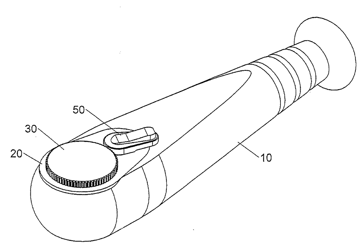
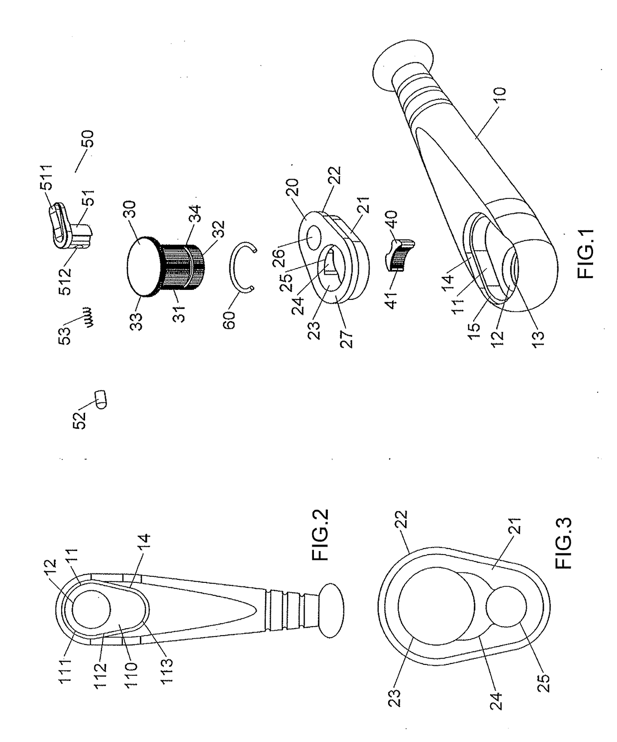
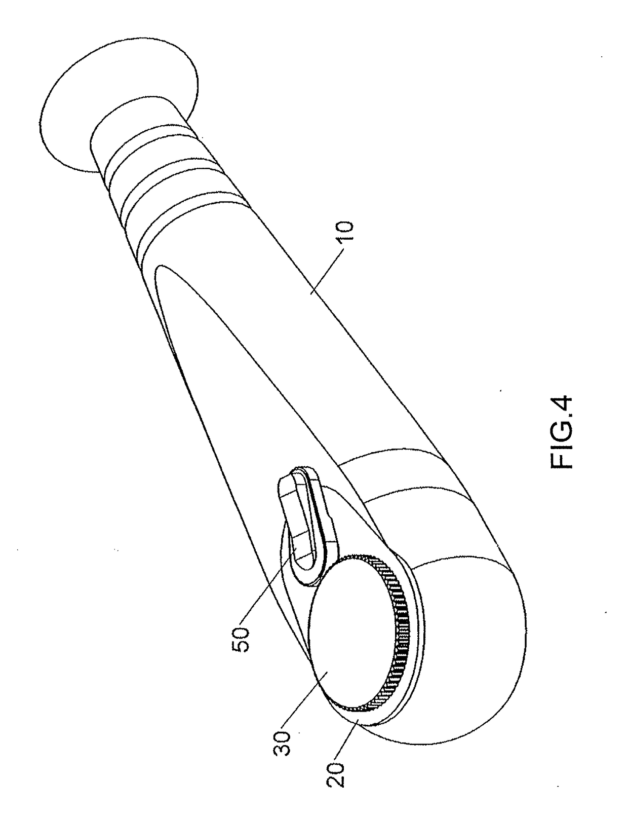
[0026]Referring to FIGS. 1 to 3, the ratchet wrench of the present invention comprises a first body 10 made of light material, such as Aluminum, Magnesium, alloy, plastic or carbon fibers. The first body 10 has a first recess 11 which has a closed bottom 110. The first recess 11 has a first side 111, a second side 112 and a third side 113, wherein the first and third sides 111, 113 each are a curved side, and the second side 112 is a straight side. The second side 112 is tangent to the first and third sides 111, 113. A first hole 12 is defined through the closed bottom 110 and shares a common axis with the first side 111. The diameter of the first side 111 is larger than that of the first hole 12. A first groove 13 is defined in the inner periphery of the first hole 12. A second recess 14 is defined in the body 10 and located above the first recess 11, and is larger than the first recess 11. A shoulder 15 is formed between the first and second recesses 11, 14. The second recess 14 i...


PUM


Abstract

A ratchet wrench includes a first body made of light material and has a first recess, a closed bottom, a first hole, a first groove, a second recess and a shoulder formed between the first and second recesses. A second body made of strong material and has a first portion and a second portion so as to be respectively received in the first and second recesses. The first portion is rested on the shoulder. A ratchet wheel and a pawl respectively received in the second body, and a switch unit is connected to the second body to operate the pawl to be engaged with the ratchet wheel. The ratchet wrench has simple structure and easily assembled and manufactured. The ratchet wrench is light and durable.

Description

BACKGROUND OF THE INVENTION[0001]1. Fields of the Invention[0002]The present invention relates to a ratchet wrench, and more particularly, to a ratchet wrench with light weight and reliable structure.[0003]2. Descriptions of Related Art[0004]One of the conventional ratchet wrenches is disclosed in U.S. Pat. No. 4,991,468 and comprises a body with a first recess and a second recess. A ratchet wheel is located in the first recess and has a toothed portion defined in the outside thereof. A bottom cover is connected to the underside of the body. A pawl is received in the second recess and has engaging teeth which are engaged with the toothed portion of the ratchet wheel. A top cover is connected to the top of the body. However, the body is made by steel which is heavy so that the user has to operate by a significant force and the heavy tool may hurt the user's wrist. Another one of the conventional ratchet wrenches is disclosed in U.S. Pat. No. 3,742,788 and which has similar drawbacks ...

Claims


Application Information

Patent Timeline
IPC IPC(8): B25B13/46
CPCB25B13/463
Inventor LIU, YI-YONG
Owner LIU YI YONG
Learn More