
Display device, timing controller and source driver

Active Publication Date: 2021-06-10
SILICON WORKS CO LTD
View PDF0 Cites 1 Cited by
  • Summary
  • Abstract
  • Description
  • Claims
  • Application Information

AI Technical Summary

Benefits of technology

The patent text describes a technology that helps reduce power consumption and EMI (electromagnetic interference) in display devices. It achieves this by repeating image data in units of pixels and supplying image data of a pixel of a preceding line again for a pixel of a current line without transmitting new image data. This means that the same image data is repeatedly supplied to multiple pixels without needing to transmit it multiple times, which saves power and reduces EMI.

Problems solved by technology

However, the transmission of the same image data may cause unnecessary transaction, and thus may increase the electromagnetic interference (EMI) and power consumption of a display device.

Method used


Image

  • Display device, timing controller and source driver
  • Display device, timing controller and source driver
  • Display device, timing controller and source driver

Examples


Embodiment Construction

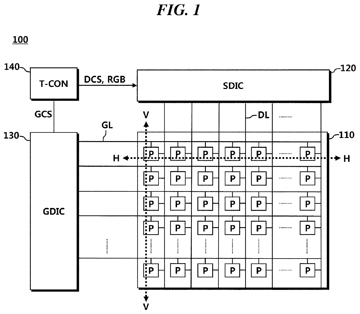
[0042]FIG. 1 illustrates the configuration of a display device according to one embodiment.

[0043]Referring to FIG. 1, a display 100 may include: a panel 110; a source driver 120; a gate driver 130; and a timing controller 140.

[0044]Multiple data lines (DLs), multiple gate lines (DL), and multiple pixels (Ps) may be arranged in the panel 110. The multiple pixels (Ps) may be disposed adjacent to each other in the horizontal direction (H) and the vertical direction (V) of the panel 110 so as to form a rectangular shape. The rectangular shape is similar to a matrix. Thus, a set of the multiple pixels (Ps) arranged in the horizontal direction (H) or a transverse line expressed thereby may be defined as a row or a line, and a set of the multiple pixels (Ps) arranged in the vertical direction (V) or a longitudinal line expressed thereby may be defined as a column.

[0045]The gate driver 130 may supply a scan signal of a turn-on voltage or a turn-off voltage to a gate line. When a scan signal...


PUM


Abstract

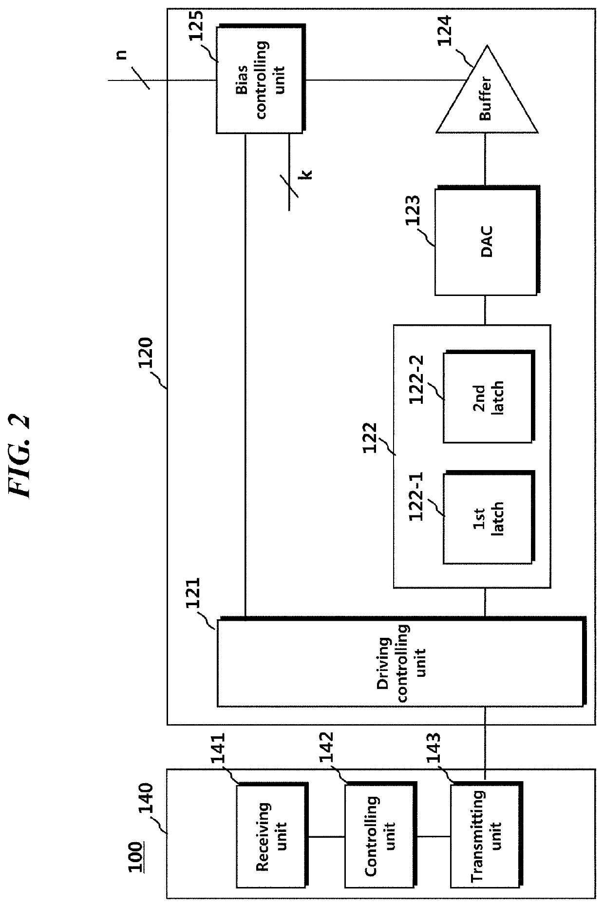
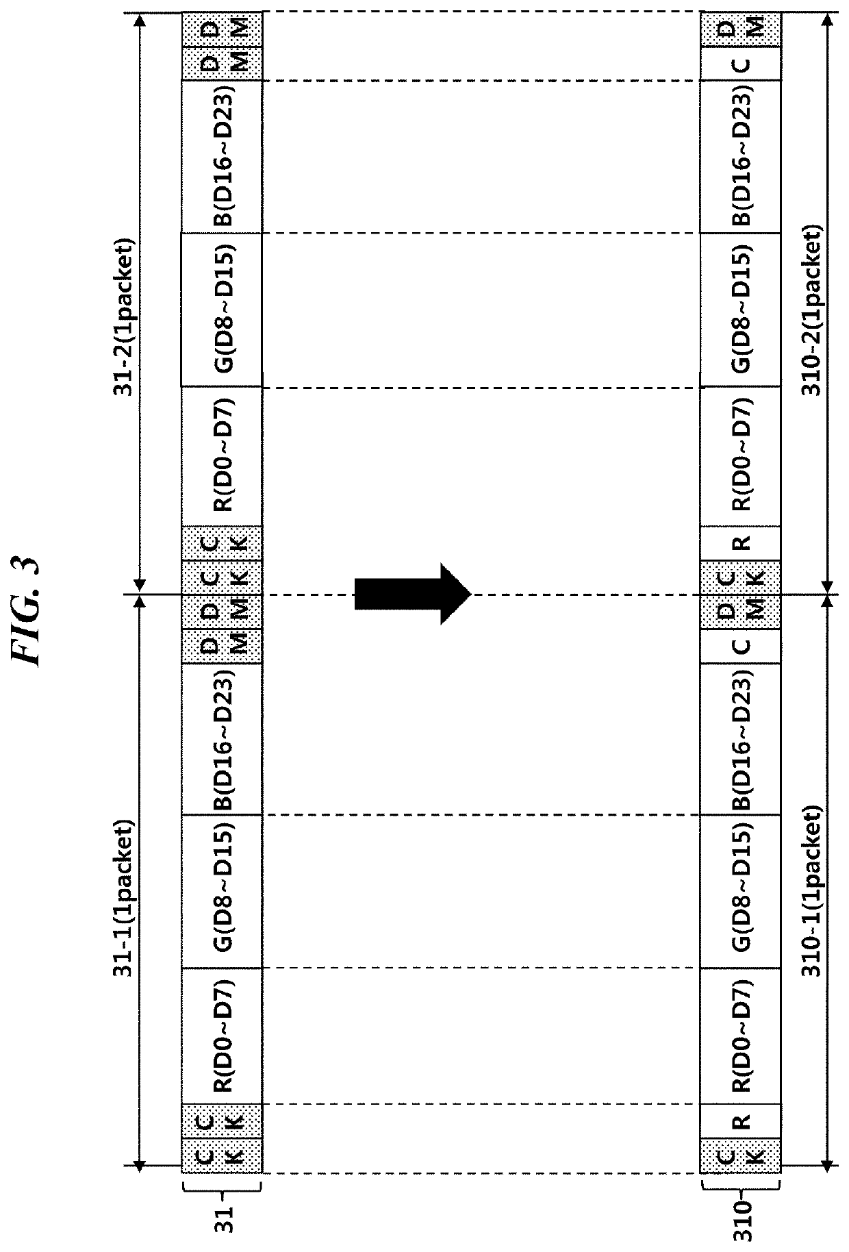
The present disclosure relates to a technology for a low power operation of a display device. The present disclosure allows reducing power consumption by supplying image data of a pixel of a preceding line again for a pixel of a current line without transmitting new image data when image data are repeated in units of pixels.

Description

CROSS REFERENCE TO RELATED APPLICATION[0001]This application claims priority from Republic of Korea Patent Application No. 10-2019-0161145, filed on Dec. 6, 2019, which is hereby incorporated by reference in its entirety.BACKGROUND1. Field of Technology[0002]The present embodiment relates to a technology for implementing low power of a display device.2. Description of the Prior Art[0003]A display device may include a panel, a source driver configured to operate a panel, and a timing controller configured to control the operation of the source driver. The panel includes multiple pixels that are arranged parallel to each other in the horizontal direction and the vertical direction and form rows and columns, wherein the multiple arranged pixels are positioned in the panel in the form of a matrix. A row formed when the multiple pixels are arranged in the horizontal direction is also called a line.[0004]The source driver may simultaneously operate multiple pixels which are present in one...

Claims


Application Information

Patent Timeline
IPC IPC(8): G09G3/20
CPCG09G3/20G09G2310/0275G09G2310/0291G09G2330/021G09G3/2074G09G2310/0248G09G2350/00G09G3/2092G09G5/003G09G2310/08G09G2310/0264G09G2310/06
Inventor CHOI, JUNG MINPARK, JONG MINOH, WOONG JIN
Owner SILICON WORKS CO LTD
Learn More