Nasal cannula device
Pending Publication Date: 2021-06-17
FOXXMED LTD
0 Cites 1 Cited by
AI-Extracted Technical Summary
Problems solved by technology
However, the nasal joint tubes of the nasal cannula device tend to bend and deform when compressed, thereby re...
Benefits of technology
[0035]Additionally, or alternatively, the side of the tubular body that is substantially longer further com...
Abstract
Disclosed herein are novel designs of a nasal cannula device suitable for supplying a flow of respiratory gas to a user during respiratory therapy. In one design, the nasal cannula device includes a cannula body, and a base. The cannula body has a front, top, and rear sides, in which the rear side is substantially longer than the front side and flattens out at both ends in the form of a wing, and a tab extending out from the lower end of the rear side. At least one nasal joint tube extends out from the top side of the cannula body, and a first connecting member is formed on the tab. The base includes, an opening formed on the top of the base; two through holes respectively formed on the left and right ends of the base; and a second connecting member formed on the bottom of the base. The first and second connecting members are configured to engage with each other thereby enclosing the base within a space collectively defined by the front, top, and rear sides, and the tab of the cannula body. In another design, the nasal cannula device includes a cannula body having a tubular body, in which one side of the tubular body is substantially longer than the rest of the tubular body and flattens out at both ends in the form of a wing, and a nasal joint tube extends out from the outer surface of the cannula body.
Application Domain
Respiratory masksMedical devices
Technology Topic
Breath treatmentBiomedical engineering +6
Image
Examples
- Experimental program(1)
Example
[0057]Detailed descriptions and technical contents of the present disclosure are illustrated below in conjunction with the accompanying drawings. However, it is to be understood that the descriptions and the accompanying drawings disclosed herein are merely illustrative and exemplary and not intended to limit the scope of the present disclosure.
[0058]1. Respiratory System
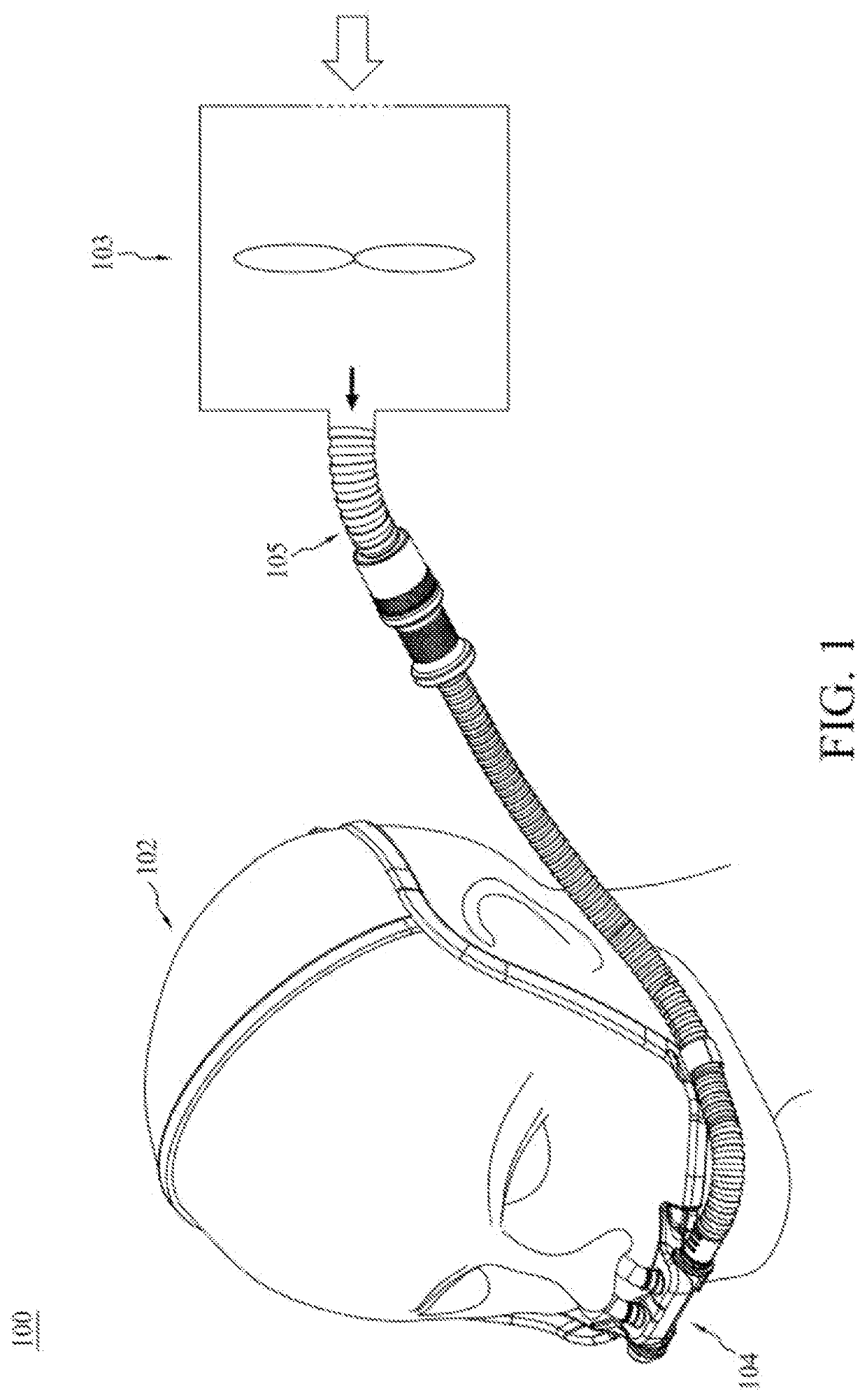
[0059]FIG. 1 is a schematic diagram of a respiratory system 100 for providing a stream of respiratory gas to a user 102 during respiratory therapy. The respiratory system 100 typically includes at least, a gas supply unit 103, a nasal cannula device 104, and a supply conduit 105, in which the supply conduit 105 is connected to the gas supply unit 103 at one end and to the nasal cannula device 104 at the other end. When in use, the gas supply unit 103 may provide a stream of gas (e.g., oxygen or air) at a pre-determined pressure, flow rate and/or humidity to the user 102 with the aid of the nasal cannula device 104, such as the one that will be described below.
[0060]2. Nasal Cannula Device
[0061]FIG. 2A is a schematic drawing of the present nasal cannula device 200 suitable for use with a respiratory system (e.g., the one depicted in FIG. 1) for providing a stream of respiratory gas to a user during respiratory therapy. The nasal cannula device 200 includes at least, a cannula body 210, a base 220, a head gear 230; and optionally, an air tube 240, and a clamp 250. The air tube 240 is coupled to one end of the base 220, and the clamp 250 helps secure the air tube 240 to the head gear 230, and at the same time, help balance the weight of the device 200 when it is worn on the user's head. In operation, when one end of the base 220 is connected to the air tube 240, then the other end of the base 220 is closed with a plug. Note that the plug is not visible from FIG. 2A.
[0062]Referring to FIG. 2B, which depicts the cannula body 210 and the base 220. The cannula body 210 has in its structure, a front side 211, a top side 212, a rear side 213, and two tabs 214 respectively extending from the lower end of the rear side 213. The rear side 213 is substantially longer than the front side 211 and flattens out at both ends in the form of a wing. The front, the top, the rear sides 211, 212, 213, and the two tabs 214 collectively define a space 215 for accommodating the base 220 therein when the cannula body 210 and the base 220 are assembled to form the device 200. Referring to FIG. 2C, which is a side view of the cannula body 210, in which the space 215 for accommodating the base 220 is revealed. Additionally, two nasal joint tubes 216 are independently formed and extended out from the top side 212 of the cannula body 210 for inserting into the nostrils of a user. Further, each tab 214 has an aperture 218 formed thereon for subsequent coupling with the base 220. Note that in this embodiment, each nasal joint tube 216 has a recessed annular section 216r recessed from its outer surface, however, in alternative embodiments, the recessed annular section 216r may be recessed from the inner surface of the tube 216, which will be described in FIG. 4.
[0063]Additionally, or alternatively, the top side 212 of the cannula body 210 may further include two recessed areas 217, in which the two nasal joint tube 216 are respectively formed and extended thereout (FIG. 3A). In some embodiments, the nasal joint tube 216 has the same thickness as that of the top side 212 of the cannula body 210 (FIG. 3B). In other embodiments, the nasal joint tube 216 has a thickness that is smaller than that of the top side 212 of the cannula body 210 (FIG. 3C). Additionally, or alternatively, the rear side 213 of the cannula body 210, which is in the form of a wing, may further include two blocking tabs 2131 respectively formed at each ends of the wing to help secure the head gear 230 in place (i.e., from moving) (FIGS. 2A, 2B, 2C and 3A).
[0064]Referring to FIG. 2B again, the base 220 of the cannula body 210 comprises in its structure, an opening 221 formed on the top of the base 220, two through holes 224 respectively formed at the left and right ends 222a, 222b of the base 220, and two protrusions 228 independently formed and extended from the bottom outer surface of the base 220.
[0065]When in use, the cannula body 210 and the base 220 are manually assembled via engaging the two protrusion 228 of the base 220 with the two apertures 218 of the tabs 214 thereby securely enclosing the base 220 within the space 215 collectively defined by the front, the top, the rear sides 211, 212, 213, and the two tabs 214 of the cannula body 210. Additionally, or alternatively, each tab 214 of the cannula body 210 may have a protrusion protruding out from its surface, while the bottom surface of the base 220 may have two corresponding apertures formed thereon, so that the two protrusions of the tabs 214 may engage with the two apertures of the base 220 thereby securely enclosing the base 220 within the space of the cannula body 210. Note that the engagement of the two protrusion 228 and the two apertures 218 also places the opening 221 of the base 220 right underneath the two nasal joint tubes 216 thereby forms an air conduit allowing the stream of gas (e.g., supplied from the gas supply unit 103 via the supply conduit 105) to pass the nasal cannula device 200 and enters the user's nostrils.
[0066]The cannula body 210 and the base 220 may be made of same or different material. Examples of the material suitable for making the cannula body 210 and the base 220 include, but are not limited to, silicone, polypropylene (PP), polyethylene (PE), polycarbonate (PC), polyvinylchloride (PVC), polycaprolactone (PCL), acrylonitrile butadiene styrene (ABS), polysulfone (PSU), polycyclohexylenedimethylene terephthalate glycol (PCTG) and the like. According to preferred embodiments of the present disclosure, the cannula. body 210 is made of silicone, while the base 220 is made of PC.
[0067]2.1 The Nasal Joint Tube
[0068]References are now made to FIGS. 4 to 6, which are schematic drawings of various forms of the present nasal joint tube, such as the one depicted in FIG. 2 or 3. In general, each nasal joint tube suitable for use in the present invention may have an inner diameter that remains constant throughout its entire length (FIG. 4, (A), (F), (G), (I) and (J)), or may be varied from one part to another (FIG. 4, (B) to (E), (H), (K) and (L)). In some embodiments, the nasal joint tube has an inner diameter that decreases gradually from its foot towards the top (FIG. 4, (C) and (D)). In other embodiments, the nasal joint tube has an inner diameter that decreases step-wisely (FIG. 4, (E)). in further embodiments, at least one part of the tube has an inner diameter that remains constant, while the other part of the tube has an inner diameter that varies gradually (FIG. 4, (B), (D), (K), and (L)).
[0069]Further, at least one section of the nasal joint tube is made less rigid or more rigid than that of the rest of the tube. In either situation, the section chosen to be modified (i.e., the section being made less or more rigid as compared to other parts of the tube) is pre-determined, preferably, modification is made to the section of the tube close to its foot.
[0070](i) Recessed and Protruded Annular Sections
[0071]To make certain section of the nasal joint tube 216 less rigid than the rest of the tube, the nasal joint tube may further include a recessed annular section 216r, which may be recessed from the outer surface or the inner surface of the nasal joint tube 216 (FIG. 4, (A) to (E), and (K) to (L)). In certain embodiments, the recessed annular section 216r is recessed in rounded form in cross section from the outer or inner surfaces of the tube 216 (FIG. 4, (A) to (D), and (K) to (L)). Preferably, the inner diameter of the nasal joint tube 216 in the recessed annular section 216r decreases gradually from its foot towards the top, while that of the other part of the nasal joint tube 216 remains constant (FIG. 4, (K) and (L)). In other embodiments, the recessed annular section 216r is recessed trapezoidally in cross section in two steps from the inner surface of the tube 216 (FIG. 4, (E)). Additionally, Of alternatively, instead of having a recessed annular section, certain section of the nasal joint tube (e.g., from the foot above certain height/length of the tube) may be made from a less rigid material or soft material (e.g., silicone), while the other part of the nasal joint tube is made from a more rigid material (e.g., PVC, PE, PCL, and etc). Alternatively, the tube may be made from same type of material having different mechanical strength (e.g., hardness), for example, certain section is made from silicon with a shore hardness of 50A, while the other part of the tube is made from silicon with a shore hardness of 30A. Still alternatively or optionally, certain section of the nasal joint tube may be made less rigid by creating one or more apertures thereon to weaken the mechanical strength of the tube (FIG. 4, (F)).
[0072]To make one section of the nasal joint tube more rigid than the rest of the tube, the nasal joint tube 216 may further include a protruding annular section 216p, which may be protruded from the outer surface or the inner surface of the nasal joint tube 216 (FIG. 4, (G) to (J)). In certain embodiments, the protruded annular section 216p protrudes in rounded form in cross section from the outer or inner surfaces of the tube 216 (FIG. 4, (G) and (H)). In other embodiments, the protruding annular section 216p protrudes perpendicularly out from the outer surfaces of the tube 216, then tapers up or down along the outer surface until it rejoins the tube body, thereby having a triangular form in cross section (FIG. 4, (I) and (J)).
[0073](II) Ribbed Section
[0074]Additionally, or alternatively, a ribbed section 216s, which comprises a plurality of parallel ribs 219, may be included in each nasal joint tube (FIG. 5).
[0075]In one preferred form, the ribbed section 216s extends around the circumferential perimeter of the nasal joint tube 216, and above the recessed annular section 216r (FIGS. 5A and 5B). Alternatively, the ribbed section 216s may also extend the full length of the tube. In another preferred form, the ribbed section 216s may be disposed right within the recessed annular section 216r (FIG. 5C), The ribbed section 216s is formed from adjacent parallel ribs 219, with the ribs 219 being parallel to the longitudinal axis of the tube 216. Each rib 219 is formed in the tube 216 by having thick-walled portions 2191 parallel to the longitudinal axis of the tube 216. The thick-walled portions 2191 are separated from adjacent thick-wailed portions 2191 by intervening thin-walled portions 2192, the thin-walled portions 2192 being parallel to the longitudinal axis of the tube 216 (i.e., around the circumferential perimeter of the tube). The thick-wailed portions 2191 alternate with the thin-walled portions 2192, thus each rib 219 is made up of one thick-walled portion 2191 with a thin-walled portion on either side (FIGS. 5D and 5E),
[0076]The thick-walled portions 2191 and the thin-wailed portions 2192 may be formed substantially circular, arc, square, rectangular, triangular or trapezoid in cross section, or may be in any desirable shape. Alternatively, the ribbed section of the tube may be formed with the outer surface of the ribbed section being smooth, and the circular, arc, square, rectangular, triangular or trapezoid-wave type ribbed profile in the inner surface of the ribbed section. Alternatively, a center line of the thick-walled portions 2191 may be aligned or offset so that the circular, arc, square, rectangular, triangular or trapezoid-wave type ribbed profile is in both the inner and outer surfaces of the ribbed section 216s.
[0077](iii) Junction Ring
[0078]Additionally, or alternatively, the nasal joint tube 216, such as the one depicted in FIGS. 2B, 5 or 6, may further include a junction ring 216j disposed around the foot of the nasal joint tube 216 (FIG. 6A). In some embodiment, the junction ring 216j has a constant height (FIG. 6B). In other embodiments, the height of the junction ring 216j varies along its top circumference or the circumference of the nasal joint tube 216 (FIG. 6C).
[0079]2.2 The Head Gear
[0080]Referring to FIG. 7, the nasal cannula device 200 also includes a head gear 230 coupled to the left and right ends 222a, 222b of the base 220. The head gear 230 includes at least, two flexible supporters 231 and an elastic fabric cover 232. Each flexible over-ear supporter 231 has two ends, in which one end has a fastener 2311 extended thereout for coupling to the left or right ends 222a, 222b of the base 220, while the other end of the over-ear supporter 231 is received in the elastic fabric cover 232. The fastener 2311 may be in the shape of a letter “C”, “D”, “O” or “U.” In the embodiment depicted in FIG. 7, each fastener 2311 has the shape of the letter “O”, capable of encircling the left or right ends 222a, 222b of the flexible supporter 231 therein. Note that the shape of the fastener 2311 is not limited to the indicated shapes, as long as it may securely couple the flexible supporter 231 to the base 220.
[0081]Returning to the elastic fabric cover 232, which is substantially in the form of a tube and has two open ends for receiving respective ends of the two supporters 231. Additionally the elastic fabric cover 232 further includes an over-head strap 2321, which help securing the head gear 230 on the user's head and stabilizing the seal created between the nasal joint tubes 216 and the user's nasal cavity, which in turn prevents inadvertent detachment of the nasal joint tubes 216 from the nasal cavity when the device 200 is in use.
[0082]3. Alternative Form of the Nasal Cannula Device
[0083]In the embodiment described in Section 2 of this paper, the nasal cannula device 200 comprises in its structure, at least a cannula body 210 and a base 220. The cannula device in this alternative embodiment differs from that in Section 2 in that it does not require the presence of a base (e.g., the base 200 as described in FIGS. 2 to 7), thereby rendering the cannula device in this alternative embodiment more compact in structure, and lighter in weight, thus is more comfortable to wear when in use.
[0084]Referring to FIG. 8, in which panel (A) is a perspective view of the cannula device 800 of this embodiment. The cannula device 800 includes, at least, a cannula body 810, a head gear 830; and optionally, an air tube 840, and a clamp 850. Note that in this embodiment, the air tube 840 is coupled to one end of cannula body 810, preferably through an adapter (not visible from FIG. 8), which will be described below. Like the function of clamp 250 described above, the clamp 850 helps secure the air tube 840 to the head gear 830, and at the same time, help balance the weight of the device 800 when it is worn on the user's head.
[0085]Turning to the cannula body 810, it has a tube-like structure with one side of the tube body being substantially longer than the other side in length and flattens out at both ends in the form of a wing (FIG. 8, (B)). The cannula body 810 comprises in its structure, a tubular body 802; and two nasal joint tubes 816, which independently extends out from the outer surface of the tubular body 802. The tubular body 802 has a hollow space 815 inside; and two open ends 804a, 804b, in which either ends 804a, 804b may be connected to the air tube 840. In operation, one end 804a, 804b of the tubular body 802 is connected to the air tube 840, while the other end 804a, 804b is dosed with a plug (not depicted). Additionally, or alternatively, an adapter (not depicted) may be used to connect the air tube 840 with either ends 804a, 804b of the tubular body 802, and the head gear 830 to the tubular body 802 as well. When the cannula body 810 is connected to the air tube 840, the hollow space 815 may serve as an air conduit allowing the stream of gas (e.g., supplied from the gas supply unit 103 via the supply conduit 105 depicted in FIG. 1) to pass the cannula body800 and enters the user's nostrils. Additionally, or alternatively, the side of the annular body 810 that is substantially longer further comprises two blocking tabs respectively formed at each ends of the wing to help secure the head gear in place.
[0086]The nasal joint tube 816 in this embodiment may be same as that described above in Sections 2.1, thus is not repeated here for the sake of brevity. As to the head gear 830, its components are substantially same as those described in Section 2.2, except in this embodiment, during assembling, the fastener of one of the two supporters may be coupled to a first adapter, then to a plug, which is used to close the end of the tubular body 802 not connected to the air tube 840; while the fastener of the other over-ear supporter may be coupled to a second adapter, in which one end of the second adapter is inserted into another open end of the tubular body 802, while the other end of the second adapter is connected to the air tube 840, thereby completes the assembling of the cannula device of this embodiment.
[0087]It will be understood that the above description of embodiments is given by way of example only and that various modifications may be made by those with ordinary skill in the art. The above specification, examples and data provide a complete description of the structure and use of exemplary embodiments of the invention. Although various embodiments of the invention have been described above with a certain degree of particularity, or with reference to one or more individual embodiments, those with ordinary skill in the art could make numerous alterations to the disclosed embodiments without departing from the spirit or scope of the present disclosure.
PUM


Description & Claims & Application Information
We can also present the details of the Description, Claims and Application information to help users get a comprehensive understanding of the technical details of the patent, such as background art, summary of invention, brief description of drawings, description of embodiments, and other original content. On the other hand, users can also determine the specific scope of protection of the technology through the list of claims; as well as understand the changes in the life cycle of the technology with the presentation of the patent timeline. Login to view more.