Backlight module and display apparatus
a backlight module and display device technology, applied in the field of viewing angle control technology, can solve problems such as leakage of confidential information, and achieve the effect of improving the convenience of operation of the display devi
- Summary
- Abstract
- Description
- Claims
- Application Information
AI Technical Summary
Benefits of technology
Problems solved by technology
Method used
Image
Examples
first embodiment
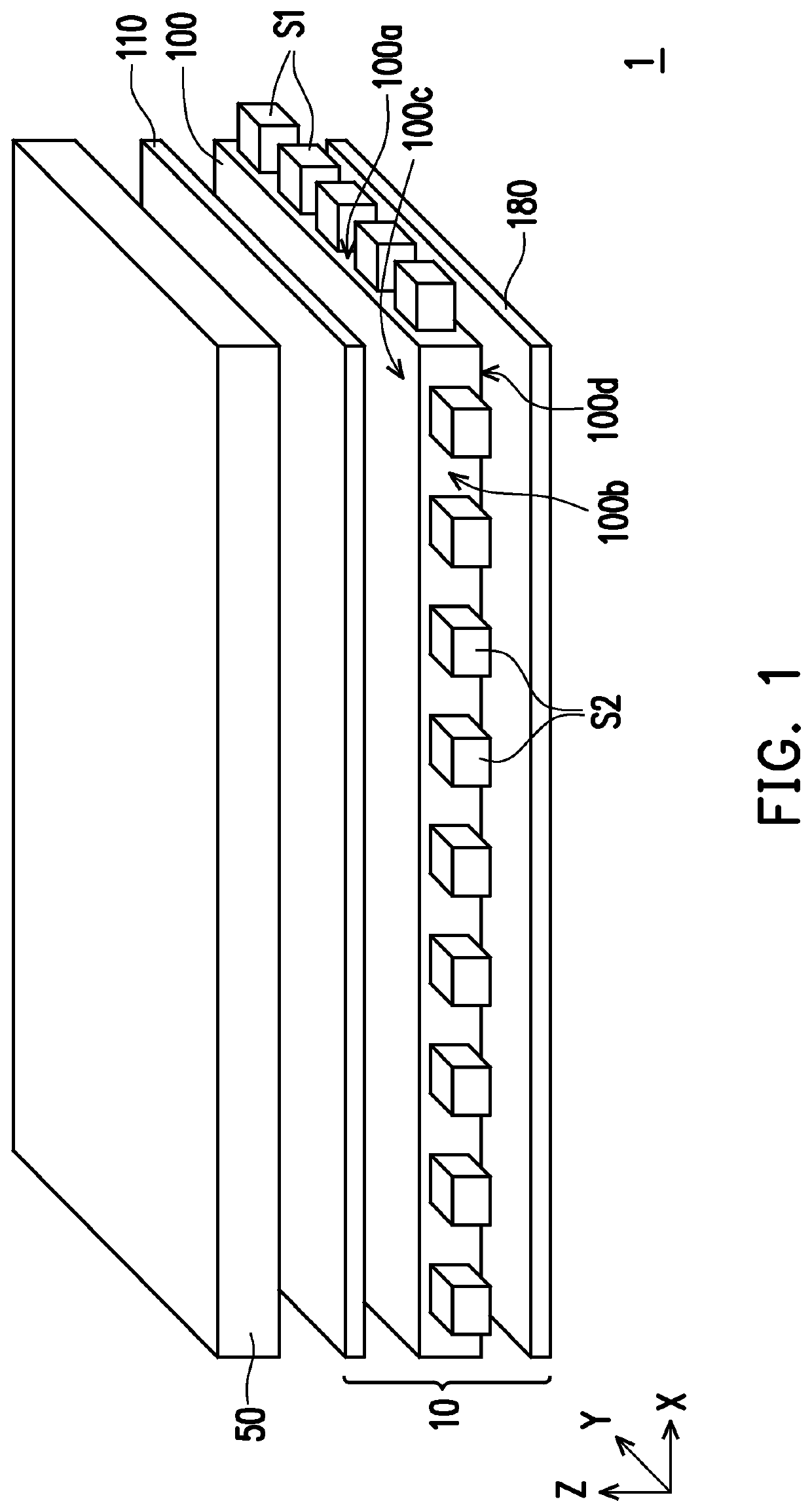
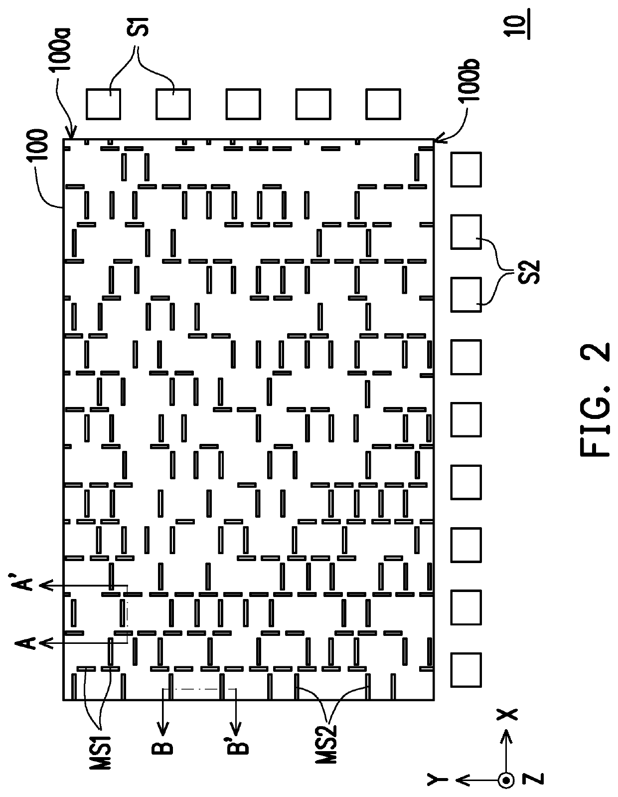
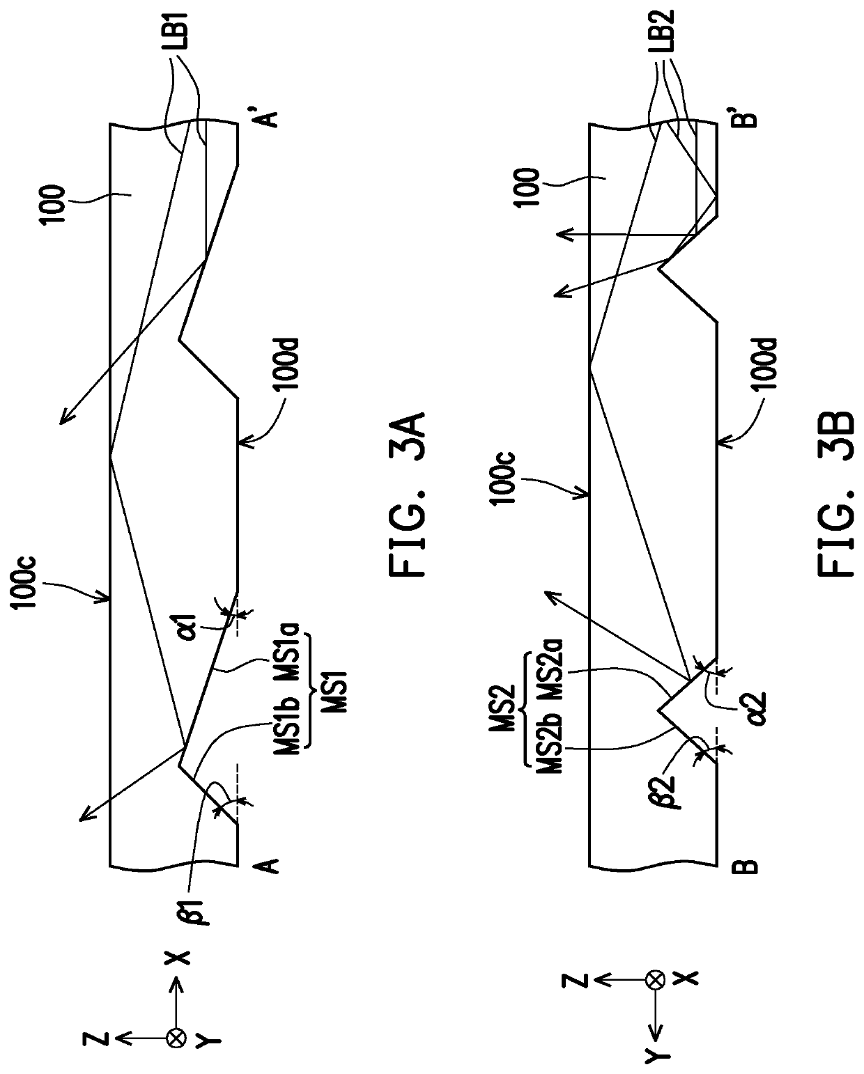
[0027]FIG. 1 is a schematic view of a display apparatus according to the invention. FIG. 2 is a schematic top view of a backlight module in FIG. 1. FIG. 3A and FIG. 3B are schematic cross-sectional views of a first optical microstructure and a second optical microstructure in FIG. 2, respectively. FIG. 4 is a graph of a viewing angle versus normalized brightness of the backlight module of FIG. 1 in different modes. In particular, FIG. 3A and FIG. 3B correspond to a section line A-A′ and a section line B-B′ in FIG. 2, respectively. For clarity, FIG. 2 omits an optical film 110 and a light absorbing sheet 180 in FIG. 1.
[0028]Referring to FIG. 1, FIG. 2, FIG. 3A, and FIG. 3B, a display apparatus 1 includes a backlight module 10 and a display panel 50. The display panel 50 is overlapped with the backlight module 10. In the embodiment, the display panel 50 is, for example, a liquid crystal display panel (LCD panel), but the invention is not limited thereto. In other embodiments, the disp...
second embodiment
[0045]FIG. 5 is a schematic view of a display apparatus according to the invention. FIG. 6 is a graph of a viewing angle versus normalized brightness of a backlight module of FIG. 5 in different modes. Referring to FIG. 5, a main difference between a display apparatus 2 in the embodiment and the display apparatus 1 in FIG. 1 lies in different optical film numbers. In the embodiment, a backlight module 11 of the display apparatus 2 further includes an optical film 120 disposed between an optical film 110 and a display panel 50. For example, the optical film 120 includes a substrate 121 and a plurality of prism structures 122. The prism structures 122 are arranged on a side surface of the substrate 121 away from a light guide member 100 in a direction Y. In other words, the optical film 120 in the embodiment may be a prism sheet, but the invention is not limited thereto.
[0046]It is worth noting that the prism pillar structures 122 extend in a direction perpendicular to a first light i...
third embodiment
[0047]FIG. 7 is a schematic view of a display apparatus according to the invention. FIG. 8 is a graph of a viewing angle versus normalized brightness of a backlight module of FIG. 7 in different modes. Referring to FIG. 7, a main difference between a display apparatus 3 in the embodiment and the display apparatus 2 in FIG. 5 lies in different optical film numbers. In particular, a backlight module 12 of the display apparatus 3 includes, in addition to an optical film 120, an optical film 130 disposed between a light guide member 100 and the optical film 120. In the embodiment, the optical film 110 may be selectively disposed between a display panel 50 and the optical film 120, but the invention is not limited thereto.
[0048]For example, the optical film 130 includes a substrate 131 and a plurality of prism structures 132. The prism structures 132 are arranged on a side surface of the substrate 131 closer to a light guide member 100 in a direction Y. The prism structures 132 extend in...
PUM
 Abstract
Description
Claims
Application Information
 - R&D
- Intellectual Property
- Life Sciences
- Materials
- Tech Scout
- Unparalleled Data Quality
- Higher Quality Content
- 60% Fewer Hallucinations
Browse by: Latest US Patents, China's latest patents, Technical Efficacy Thesaurus, Application Domain, Technology Topic, Popular Technical Reports.
© 2025 PatSnap. All rights reserved.Legal|Privacy policy|Modern Slavery Act Transparency Statement|Sitemap|About US| Contact US: help@patsnap.com


