Dynamic seal

a technology of resilient metallic seals and sealing plates, applied in the direction of engine seals, mechanical equipment, engine components, etc., can solve the problems of reducing the service life of the seal, requiring special and costly wear protective coatings, and requiring frequent refinishing, etc., to reduce or eliminate wear.

Active Publication Date: 2021-07-01
SAINT GOBAIN PERFORMANCE PLASTICS CORP
View PDF1 Cites 1 Cited by
  • Summary
  • Abstract
  • Description
  • Claims
  • Application Information

AI Technical Summary

Benefits of technology

[0003]Embodiments of the present invention relate in general to a dynamic, resilient metallic seal for the containment of pressurized fluids, including gases, from cryogenic to highly elevated temperatures where thermal expansion is anticipated, and more particularly, to a dynamic metal seal for isolating one or more fluids in an annulus formed between two approximately concentric tubular members or opposed axially facing surfaces permitting reciprocating axial, radial, or lateral offset or angular displacement and misalignment capability between the concentric tubular members. The seal, by eliminating sliding motion during reciprocating axial displacement due to mechanical, vibrational, thermal, or other loads, reduces or eliminates wear between the outer tubular member and the inner tubular member and their respective seal interfaces.

Problems solved by technology

The sealing interface is typically generated by interference fits between the seal and the concentric tubular members.
Thermal, mechanical, and vibrational forces can cause relative displacement between the seal and one or both tubular members during operation.
This relative displacement can result in wear in one or more of the tubular members and / or the seal, thereby requiring special and costly wear protective coatings, costly diameter and surface finish requirements, and / or frequent refinishing.

Method used


Image

  • Dynamic seal
  • Dynamic seal
  • Dynamic seal

Examples


examples

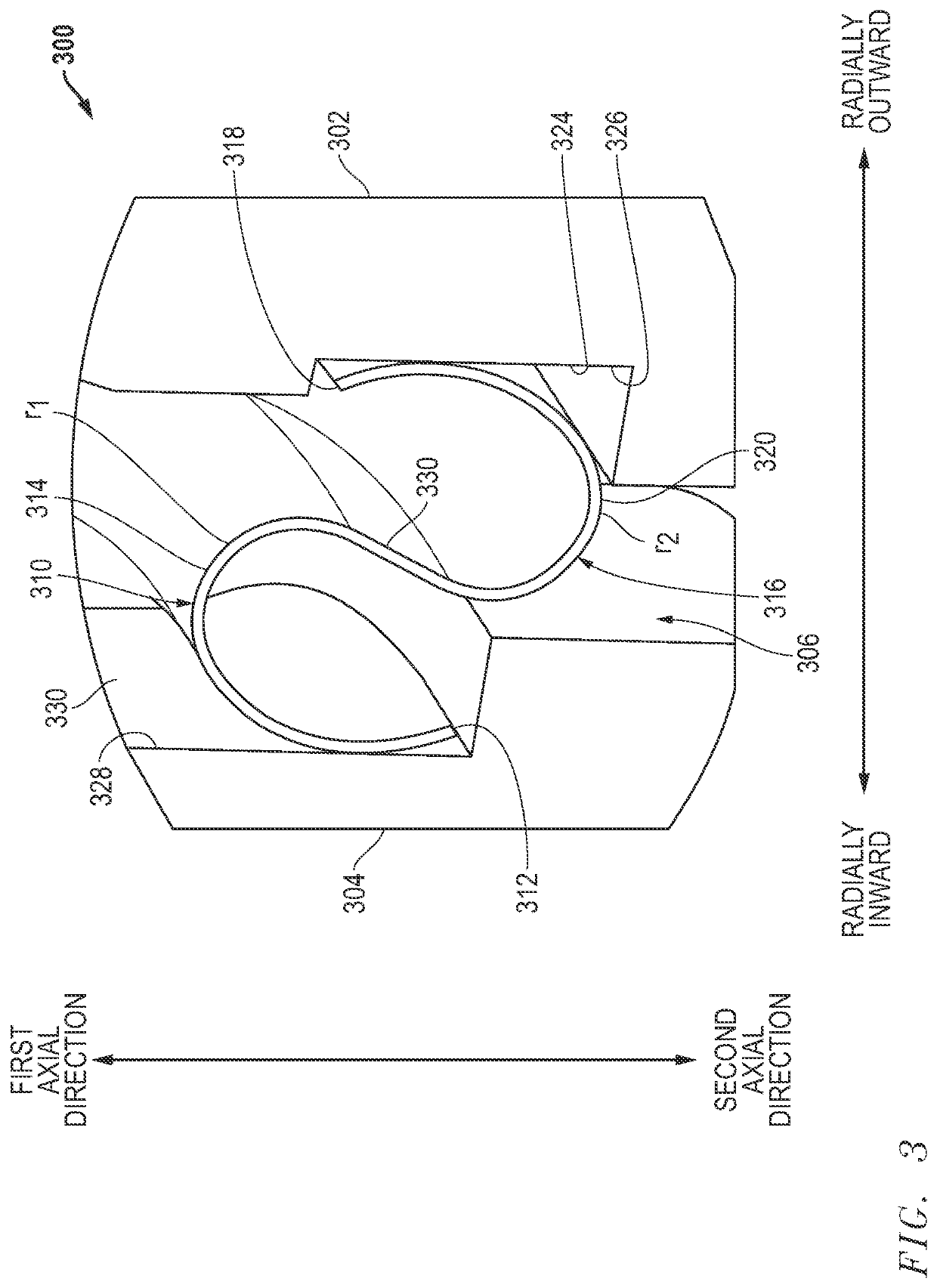
[0074]A traditional annular seal (C1) and an exemplary embodiment (S1) of an annular seal 308 were each installed in identical fixtures in an annulus formed between an inner tubular member and an outer tubular member. Pressure of 0.69 MPa (100 psi) was applied to each of the fixtures, and the inner tubular member was displaced radially until the annular seals began to lose contact with the outer tubular members. Each of C1 and S1 maintained contact pressure at a displacement of 0.07 mm. C1 began to lose contact pressure with the outer tubular member at a displacement of 0.08 mm, and the loss of contact pressure increased at a displacement of 0.09 mm. S1 maintained contact pressure at a displacement of 0.09 mm and began to lose contact pressure with the outer tubular member at a displacement of 0.12 mm. Thus, under similar conditions and displacement, S1 outperformed C1 in terms of maintaining contact pressure with the outer tubular member and is more resistant to displacement than C...


PUM


Abstract

Systems and methods are disclosed that include providing an outer tubular member, an inner tubular member telescopically disposed within the outer tubular member, and an annular seal disposed between the outer tubular member and the inner tubular member, the annular seal being resilient to permit relative movement between the outer tubular member and the inner tubular member, and the annular seal having in a radial cross-section: a first annular leg portion terminating at an end that is radially inward or radially outward, the first annular leg portion comprising a first open loop; and a second annular leg portion extending from the first annular leg portion and terminating at an end that is the other of radially inward or radially outward, the second annular leg portion comprising a second open loop.

Description

CROSS-REFERENCE TO RELATED APPLICATION(S)[0001]This application claims priority under 35 U.S.C.§ 119(e) to U.S. Provisional Application No. 62 / 954,058, entitled “DYNAMIC SEAL,” by Mark W. ARMITAGE et al., filed Dec. 27, 2019, which is assigned to the current assignee hereof and incorporated herein by reference in its entirety.BACKGROUND OF THE INVENTION[0002]Traditional seals, such as axial c-ring seals and other lipseals are suitable for sealing between two approximately concentric tubular members. The sealing interface is typically generated by interference fits between the seal and the concentric tubular members. Thermal, mechanical, and vibrational forces can cause relative displacement between the seal and one or both tubular members during operation. This relative displacement can result in wear in one or more of the tubular members and / or the seal, thereby requiring special and costly wear protective coatings, costly diameter and surface finish requirements, and / or frequent r...

Claims


Application Information

Patent Timeline
Patent Type & Authority Applications(United States)
IPC IPC(8): F16J15/3284
CPCF16J15/3284F16J15/0887
Inventor ARMITAGE, MARK W.GEORGE, DOUGLAS
Owner SAINT GOBAIN PERFORMANCE PLASTICS CORP
Why Eureka
Try Eureka