Liquid ring pump control

a technology of liquid ring pump and control ring, which is applied in the direction of liquid fuel engines, rotary piston liquid engines, machines/engines, etc., can solve the problems of cavitation, wear and failure of certain liquid ring pumps, and the liquid ring pumps can consume considerable amounts of fresh water, so as to reduce the operating cost of the liquid ring pump, reduce the operating cost, and reduce the effect of wear

Pending Publication Date: 2021-01-28
EDWARDS TECH VACUUM ENG QINGDAO CO LTD
View PDF3 Cites 0 Cited by
  • Summary
  • Abstract
  • Description
  • Claims
  • Application Information

AI Technical Summary

Benefits of technology

[0008]The present inventors have realised it is desirable to provide for controlling of operating liquid temperature and / or pressure of a liquid ring pump in a way that minimises operating liquid and power consumption. Such control advantageously tends to reduce operating costs of the liquid ring pump.
[0009]The present inventors have further realised it is desirable to provide for controlling of a liquid ring pump in a way that prevents or opposes cavitation in that liquid ring vacuum pump. Cavitation tends to be a significant cause of wear and failure in certain liquid ring pumps, especially those operating at a low-pressure / high-vacuum condition. Such control advantageously tends to reduce or eliminate wear caused by cavitation.

Problems solved by technology

Accordingly, liquid ring pumps can consume considerable amounts of fresh water.
Cavitation tends to be a significant cause of wear and failure in certain liquid ring pumps, especially those operating at a low-pressure / high-vacuum condition.

Method used


Image

  • Liquid ring pump control
  • Liquid ring pump control
  • Liquid ring pump control

Examples


Embodiment Construction

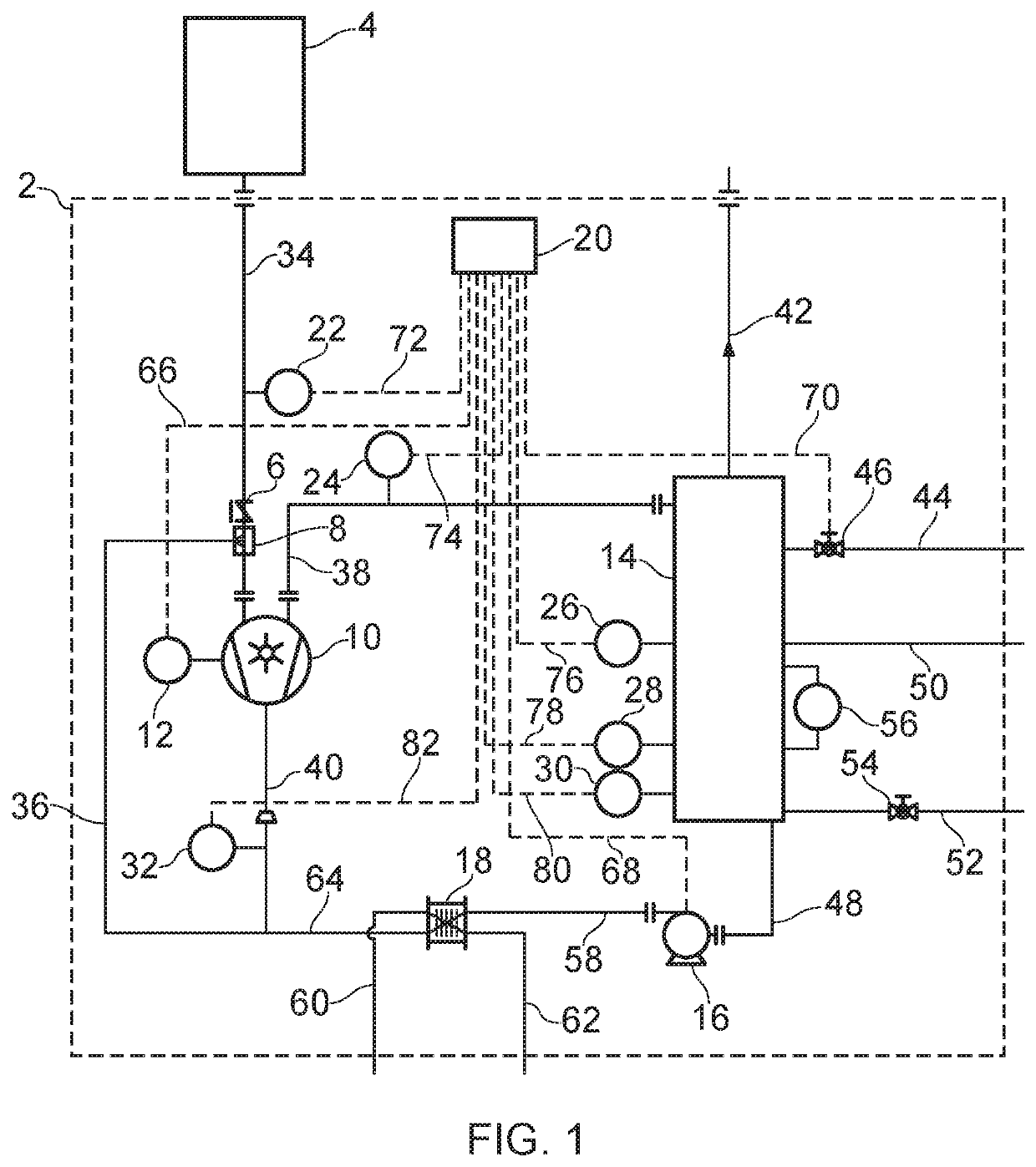
[0024]FIG. 1 is a schematic illustration (not to scale) showing a vacuum system 2. The vacuum system 2 is coupled to a facility 4 such that, in operation, the vacuum system 2 establishes a vacuum or low-pressure environment at the facility 4 by drawing gas (for example, air) from the facility 4.

[0025]In this embodiment, the vacuum system 2 comprises a non-return valve 6, one or more spray nozzles 8, a liquid ring pump 10, a motor 12, a separator 14, a pump system 16, a heat exchanger 18, a controller 20, a first pressure sensor 22, a first temperature sensor 24, a second pressure sensor 26, a first level sensor 28, a second level sensor 30, and a second temperature sensor 32.

[0026]The facility 4 is connected to an inlet of the liquid ring pump 10 via a suction or vacuum line or pipe 34.

[0027]The non-return valve 6 and the spray nozzle are disposed on the suction line 34. The non-return valve 6 is disposed between the facility 4 and the spray nozzle 8. The spray nozzle 8 is disposed ...


PUM


Abstract

A control system comprising: a suction line; an exhaust line; an operating liquid line; a liquid ring pump comprising a suction input coupled to the suction line, an exhaust output coupled to the exhaust line, and a liquid input coupled to the operating liquid line; one or more regulating devices configured to control flow of the operating liquid into the liquid ring pump; a first sensor configured to measure a first parameter of an exhaust fluid of the liquid ring pump; a second sensor configured to measure a second parameter of an operating liquid received by the liquid ring pump; and a controller operatively coupled to the sensors and the regulating device(s), and configured to control the regulating device(s) based on measurements by the sensors.

Description

[0001]This application is a national stage entry under 35 U.S.C. § 371 of International Application No. PCT / IB2019 / 052066, filed Mar. 14, 2019, which claims the benefit of GB Application 1804108.7, filed Mar. 14, 2018. The entire contents of International Application No. PCT / IB2019 / 052066 and GB Application 1804108.7 are incorporated herein by reference.TECHNICAL FIELD[0002]The present disclosure relates to the control of liquid ring pumps.BACKGROUND[0003]Liquid ring pumps are a known type of pump which are typically commercially used as vacuum pumps and as gas compressors. Liquid ring pumps typically include a housing with a chamber therein, a shaft extending into the chamber, an impeller mounted to the shaft, and a drive system such as a motor operably connected to the shaft to drive the shaft. The impeller and shaft are positioned eccentrically within the chamber of the liquid ring pump.[0004]In operation, the chamber is partially filled with an operating liquid (also known as a ...

Claims


Application Information

Patent Timeline
Patent Type & Authority Applications(United States)
IPC IPC(8): F04C25/02
CPCF04C25/02F04C28/24F04C27/02F04C28/28F04C28/08F04C19/007F04C19/004F04C2270/0525F04C2270/185F04C2270/195F04C2240/81F04C2270/24F04C2270/40F04C19/001F04C7/00F04C28/00F04C2270/205F04C2270/225F04C19/00F04C2270/18F04C2270/19F04C2270/21F04C2270/22F04C2270/42F04C2270/46F04D17/10F04D27/00F04D29/083
Inventor COECKELBERGS, JOERIDE BOCK, ANDRIES DANIEL JOZEFGLAISTER, MARK GORDON
Owner EDWARDS TECH VACUUM ENG QINGDAO CO LTD
Why Eureka
Try Eureka