Powder bed fusion apparatus

a technology of fusion apparatus and powder bed, which is applied in the direction of additive manufacturing process, manufacturing tools, manufacturing environment conditioning, etc., can solve the problems of powder to be ejected from the powder bed, and the presence of excess powder at the end of each layer formation

Pending Publication Date: 2021-07-08
RENISHAW PLC
View PDF6 Cites 6 Cited by
  • Summary
  • Abstract
  • Description
  • Claims
  • Application Information

AI Technical Summary

Benefits of technology

[0012]In this way, powder, such as excess powder dosed during layer formation or powder of the powder bed recovered during a de-build of the object can be recovered to the gas circuit without having to move the exhaust. In this regard, the exhaust channel or opening may have a fixed location in the build chamber.
[0013]The layer formation device may be arranged to form layers of powder in a working plane and the exhaust channel or opening may be located at or below the working plane. In this way, the powder does not need to be lifted for recovery into the exhaust.
[0019]The layer formation device may comprise a hopper from which powder is dosed in a controlled manner to be formed into the layers, for example, by being spread by a wiper. The separator may be located above the hopper such that powder falls from the separator into the hopper. For the avoidance of doubt, such an arrangement may be provided in addition to or independently from a location of the exhaust channel or opening in the build chamber. The hopper may be arranged to dose powder into the build chamber from above the working plane and powder is conveyed from the exhaust up to the separator by the gas flow. In this way, the gas flow may act, in the build chamber, as a gas knife for maintaining the atmosphere in the build chamber free from gas borne particles and, in the gas circuit, as a powder conveyor for conveying the powder to a location for subsequent dispense. Accordingly, a powder conveying system separate from the gas circuit for generating the gas knife may not be required.
[0029]The outlet of the feeding tube may be arranged such that, without gas flow, powder builds-up in the conduit pipe below the outlet to block the outlet to further powder flow without blocking a full cross-section of the conduit pipe. In this way, gas is not prevented from flowing through the conduit pipe by the powder fed into the conduit pipe.
[0031]In this way, the device automatically controls the flow of powder from the hopper, based upon whether the motive force is carrying the powder away to maintain the channel unblocked.

Problems solved by technology

A problem posed by such devices is how to recover powder that is not consolidated for a subsequent build.
First, the impact of the laser with the powder bed can cause powder to be ejected from the powder bed.
However, this leads to the presence of excess powder at the end of each layer formation.

Method used


Image

  • Powder bed fusion apparatus
  • Powder bed fusion apparatus
  • Powder bed fusion apparatus

Examples


Embodiment Construction

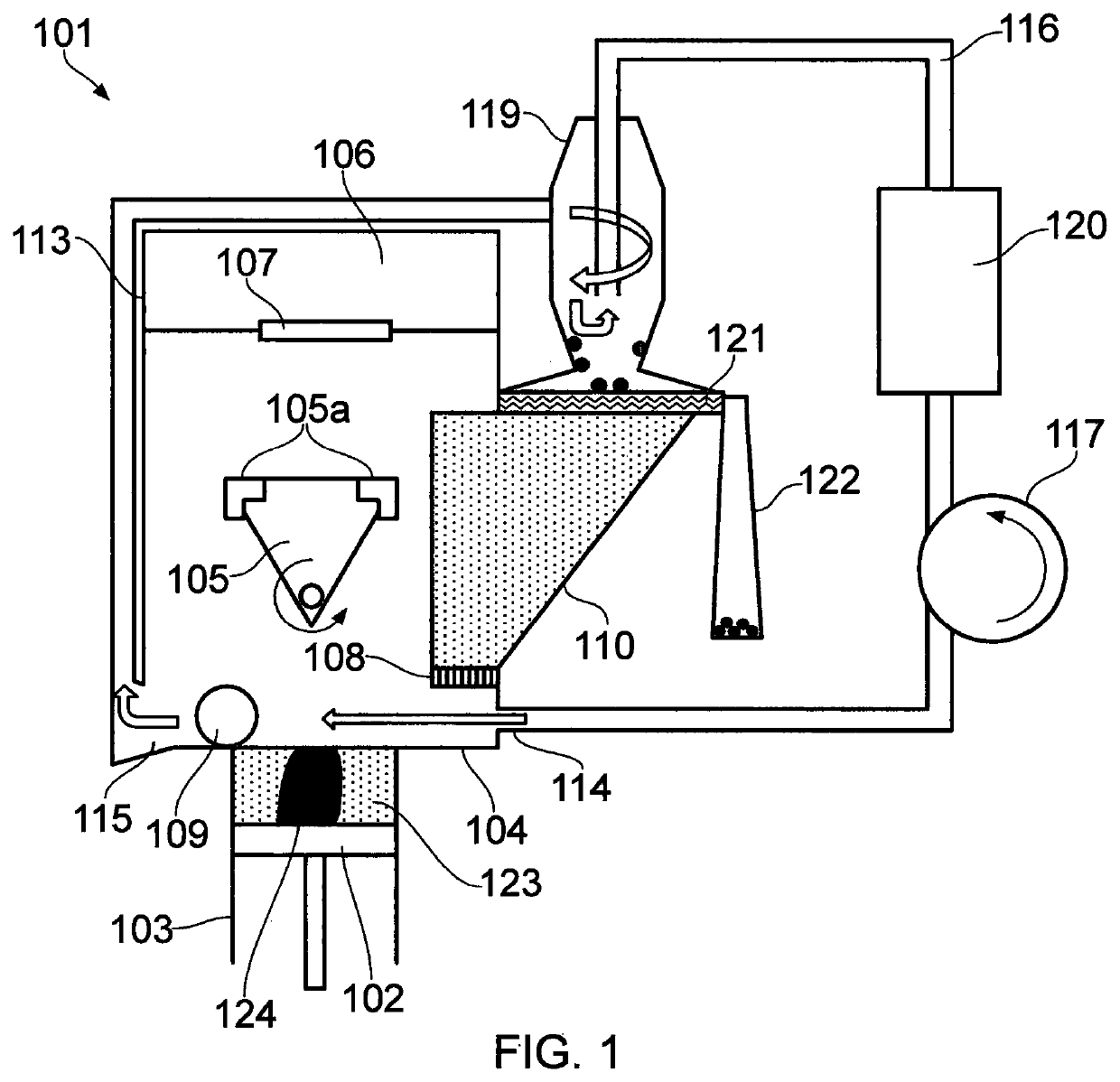
[0042]Referring to the Figures, a powder bed fusion apparatus 101 according to one embodiment of the invention comprises a build platform 102 movable within a build sleeve 103 to define a build volume, a layer formation device for forming layers of powder across the build volume in a working plane and a scanner 106 for directing a laser beam through an optical window 107 and steering the laser beam across the working plane to selectively fuse the powder. Successive formation of powder layers forms a powder bed 123 in the build volume.

[0043]The layer formation device typically comprises a doser 108 for dosing powder and a wiper 109 for spreading the dosed powder into a layer. In this embodiment, the doser is a top-doser, which doses powder from a hopper 110 onto surface 104. The doser 108 may be in accordance with that disclosed in WO2010 / 007396. A lower edge of the wiper defines the working plane and is substantially aligned with the surface 104.

[0044]A build chamber 113 is provided...


PUM

PropertyMeasurementUnit
diameteraaaaaaaaaa
sizeaaaaaaaaaa
particle size distributionsaaaaaaaaaa

Abstract

A powder bed fusion apparatus including a build chamber, a build platform in the build chamber for supporting a powder bed, a layer formation device for forming layers of powder to form the powder bed, a scanner for scanning an energy beam across the powder bed to fuse the powder and a gas circuit for forming a gas flow across the powder bed. The gas circuit includes a separator for separating particles from gas in the gas circuit, a nozzle for propelling gas into the build chamber and an exhaust for extracting gas from the build chamber and delivering the gas to the separator. The exhaust includes an exhaust channel or opening located for receiving powder wiped from the powder bed and / or build platform.

Description

FIELD OF INVENTION[0001]This invention concerns powder bed fusion apparatus and, in particular, but not exclusively, powder bed fusion apparatus in which a laser is used to consolidate powder of a powder bed in a controlled, typically inert, atmosphere.BACKGROUND[0002]Powder bed fusion apparatus produce objects through layer-by-layer solidification of a material, such as a metal powder material, using a high energy beam, such as a laser or electron beam. A powder layer is formed across a powder bed contained in a build sleeve by lowering a build platform to lower the powder bed, depositing a heap of powder adjacent to the lowered powder bed and spreading the heap of powder with a wiper across (from one side to another side of) the powder bed to form the layer. Portions of the powder layer corresponding to a cross-section of the workpiece to be formed are then solidified through irradiating these areas with the beam. The beam melts or sinters the powder to form a solidified layer. Af...

Claims


Application Information

Patent Timeline
Patent Type & Authority Applications(United States)
IPC IPC(8): B23K26/342B23K26/04B23K26/082B23K26/12B23K26/144B23K26/14B23K26/16B23K26/70B22F10/28B22F12/70B22F10/73B33Y30/00B33Y40/00
CPCB23K26/342B23K26/04B23K26/082B23K26/127B23K26/144B23K26/1464B33Y40/00B23K26/702B22F10/28B22F12/70B22F10/73B33Y30/00B23K26/16B22F2999/00B33Y10/00B29C64/153B29C64/35B29C64/371Y02P10/25B22F10/322B22F10/68B22F10/77B29C64/364B22F2202/17
Inventor BEEBY, DAVID EDWARDWHITTON, DAVID JOHNCRITCHLEY, ANDREW THOMAS
Owner RENISHAW PLC
Why Eureka
Try Eureka