Connector device

Pending Publication Date: 2021-07-08
OURIP PTY LTD
View PDF0 Cites 1 Cited by
  • Summary
  • Abstract
  • Description
  • Claims
  • Application Information

AI Technical Summary

Benefits of technology

The invention is a connector assembly that is designed to improve the user experience by addressing common challenges associated with existing connectors. It does this by using lever operated cams or user sliding locks to achieve linear actuation of the connectors. In one embodiment, the connector assembly allows for secure placement while in another embodiment, the outer housing is securely fixed to the spout during placement. The inner and outer housings function to provide the linear actuation of the connector assembly with reduced or no movement of the inner housing during actuation. The material selected for the connector assembly can alter the force required to actuate it and other components can be added to adapt the actuation for a particular purpose. The actuating means can secure the actuator assembly to the inner housing, the outer housing, or the connector. Overall, the connector assembly improves the sealing quality with the spout and provides a better user experience.

Problems solved by technology

Historically, such low cost beverages were less tolerated in the marketplace and were viewed upon by patrons as inferior products.
It will be readily apparent that the practical difficulties in cleansing or sanitising hoses, connectors and dispensing equipment causes venues to maintain dedicated lines for individual varieties of post-mix beverages.
Further, dispensing equipment such as “bar guns” are typically limited to a fixed number of dispensing outlets.
Consequently, many venues cannot offer patrons the variety of post-mix beverages that are available in the marketplace, and frequently smaller boutique beverage producers miss the opportunity to supply post-mix variations of their beverage products.
However, the custom configuration of “Bag-In-Box” spouts or their connectors may pose a further impediment to these venues switching beverage varieties.
Several mechanical issues arise from the use of each of these connectors, many of which are interrelated, and lead to operational difficulties for the user.
First, users frequently experience difficulty engaging a threaded attachment on the liquid container packaging.
A challenge to either or both of these events frequently arises when the threaded arrangement on the packaging, or either mating end, becomes damaged, soiled, twisted or becomes weakened.
This may result in substantial force being needed to be exerted on the spout or on the soft packaging upon which the spout is mounted.
This issue also arises in the use of snap on connectors, which must align with and be placed within the spout opening if successful engagement is to take place when the connector is “snapped” on.
However, the force and handling increase the risk of damage to the spout or packaging.
For example, the spout may easily be torn from the package or damaged to an extent causing a leak between the spout and the package.
Frequently, too little grip area is available on the spout to withstand the force required by the user.
In turn, the unfortunate slippage of the tool may also result in damage of the spout or packaging.
The tool may slip and puncture the packaging or the bulk of the bag or packaging may impede or otherwise obstruct the needed manipulation when working with the assembled equipment.
There is also a significant risk in the use of existing connectors as soil, dirt or other foreign material that may find its way on to the spout or connector may impede the secure engagement of the connector.
Such foreign material may impede proper threading, damage the thread or impede alignment of snap on fittings.
For instance, threads may become stripped or cross threaded whereby the distortion of the components caused by the cross threading may result in the leakage of the product.

Method used


Image

  • Connector device
  • Connector device
  • Connector device

Examples


Embodiment Construction

[0061]Several embodiments are described in detail below with reference to the figures. Exemplary embodiments are described to illustrate certain aspects and embodiments of the invention, not to limit its scope, which is defined by the claims. Those of ordinary skill in the art will recognise that a number of equivalent variations of the various features provided in the description that follows may be possible.

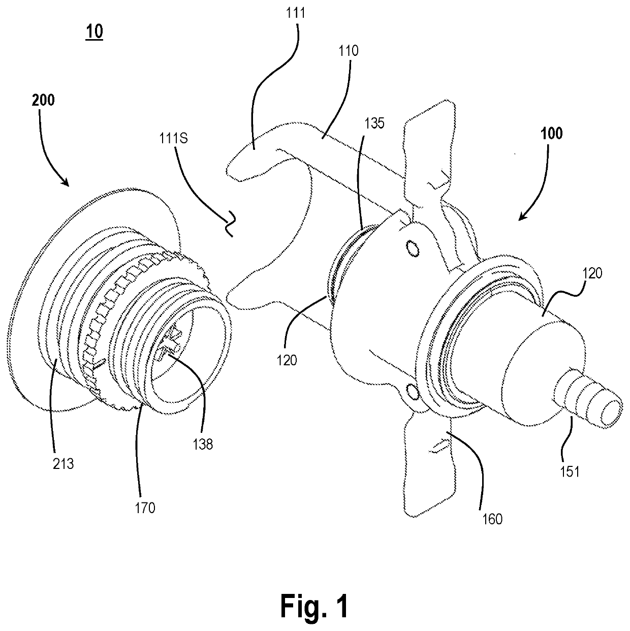
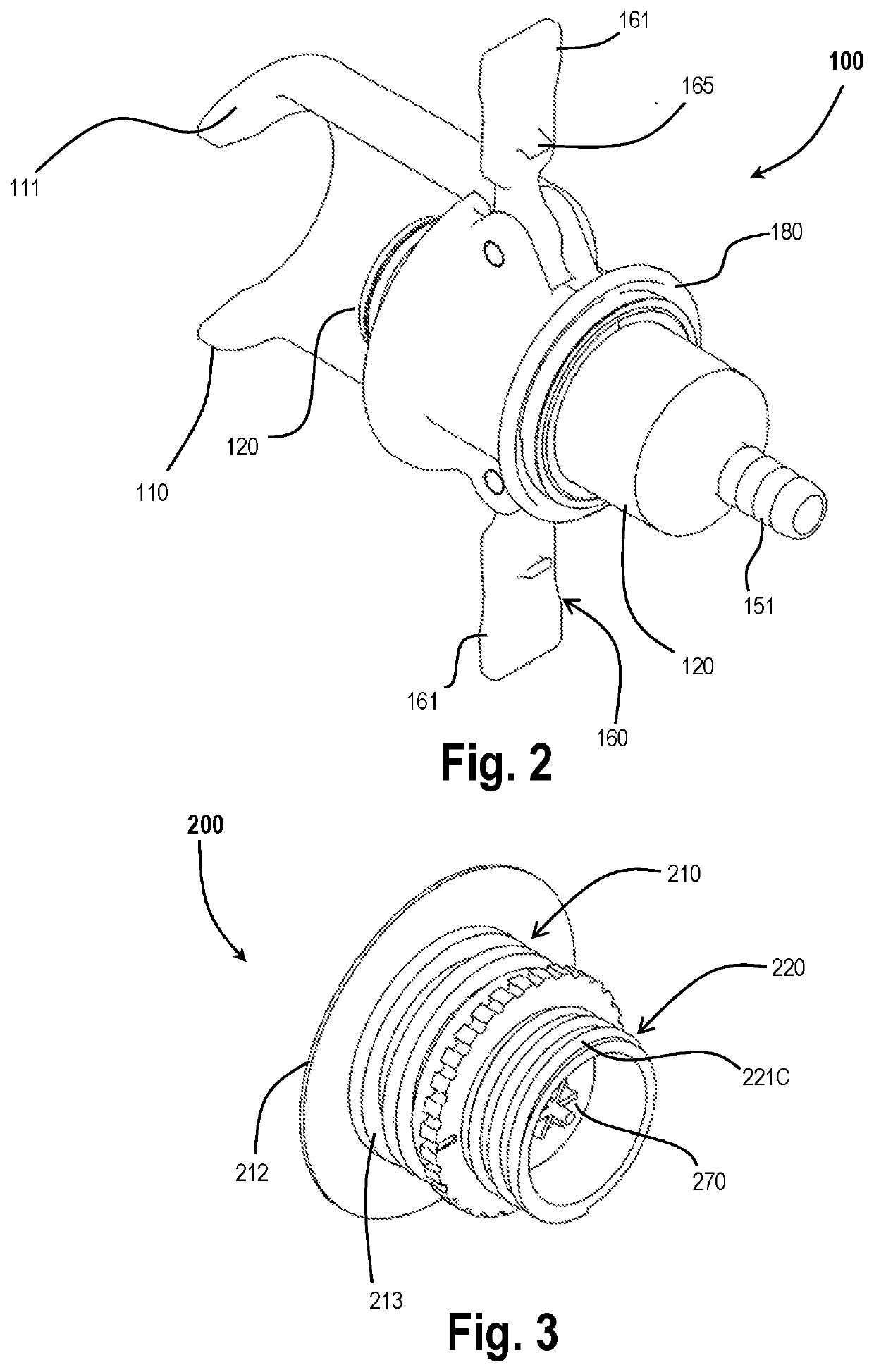
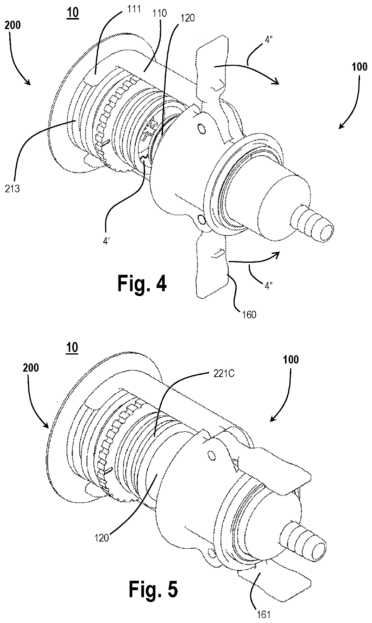
[0062]FIG. 1 is a perspective view of a connector assembly 10, in accordance with at least one embodiment of the disclosure. The connector assembly 10 may include a connector 100 and a spout assembly 200.

[0063]The connector 100 includes an outer housing 110 and an inner housing 120. The outer housing 110 may be adapted to be secured onto the spout assembly 200. In particular, the outer housing 110 may be provided with a spout assembly engagement collar 111. The spout assembly engagement collar 111, in one embodiment, is secured to the spout assembly 200 by sliding the spout ass...


PUM


Abstract

Various aspects of the invention described herein relate to a removable connector assembly, and methods of use and manufacture thereof. More particularly, certain embodiments relate to apparatus and methods to provide a connection to a spout disposed upon a container, such as upon a bag holding fluid. Embodiments of connector assemblies comprise an elongated outer housing, an inner housing, and a slider assembly for moving the outer surface of the sleeve member over the inner surface of the outer housing wall in a lengthwise motion to position the spout connector upon the spout and secure the spout connector in said position.

Description

TECHNICAL FIELD[0001]Various aspects of the invention described herein relate to a removable connector assembly, and methods of use and manufacture thereof. More particularly, certain embodiments relate to apparatus and methods to provide a connection to a spout assembly disposed upon a container, such as upon a bag holding fluid.BACKGROUND[0002]“Bag-In-Box” flexible liquid packaging has been used for the packaging and shipping of post-mix syrup to restaurant, pubs and clubs (and other retailers) for many years. In general, this form of packaging includes a plastic bag containing the syrup product, placed within a corrugated box that provides a protective housing to ease the transportation, distribution and storage of post-mix syrup during use.[0003]“Bag-In-Box” packaging has enabled manufacturers of beverages, particularly cold carbonated beverages, to distribute their product more broadly and to provide a low cost product to restaurant, pubs and clubs. These venues, in turn, suppl...

Claims


Application Information

Patent Timeline
IPC IPC(8): B67D1/08B65D47/24B65D77/06B67D1/00B67D1/12
CPCB67D1/0807B65D47/249B65D77/068B67D2001/0827B67D1/0021B67D1/1277B67D1/0001B67D7/0294B67D1/0462B65D77/067B67D2001/0093B67D1/0079F16L37/18F16L37/26F16L37/36B67D3/043B67D2210/00062
Inventor EDWARDS, SIMON
Owner OURIP PTY LTD
Why Eureka
Try Eureka