Method and apparatus for dielectric isolation of fuel cells

Inactive Publication Date: 2006-08-24
CONNECTICUT INNOVATIONS
View PDF4 Cites 3 Cited by
  • Summary
  • Abstract
  • Description
  • Claims
  • Application Information

AI Technical Summary

Benefits of technology

[0020] Embodiments of the present invention are directed to fuel cell stack housing assemblies which provide for the dielectric isolation of fuel cell stacks. Aspects of certain embodiments of the present invention are particularly advantageous in that they reduce the occurrence of short circuits than can result between the electrical poles, or between any other positions on the fuel cell stack that have an electronic potential generated by a fuel cell reaction. Such short circuits can be disadvantageous in that they tend to draw down the fuel cell electrical potential thereby reducing the output power and the electrical efficiency of the fuel cell.
[0022] According to one embodiment of the present invention, the first and second housing sections each include respective flanges angled outwardly and to the exterior of the housing section. The flanges are connected opposite to one another to form the housing for the fuel cell stack. Positioned between the flanges is a dielectric medium. Together the flanges and the dielectric medium form a dielectric joint between the first and second housing sections. In accordance with one aspect, the position of the opposing flanges and dielectric medium, which can be in the form of a strip, relative to the major un-grounded electrical terminal of the fuel cell stack is selected to eliminate the influence of migratory liquid electrolyte on the dielectric qualities of the dielectric joint.
[0024] According to a certain aspect of the present invention, the first and second housing sections are removably secured to one another. This is advantageous should the fuel cell stack need repair or the dielectric medium need replacing. According to one embodiment, the first housing section flange and the second housing section flange are removably connected to one another by a plurality of removable fasteners. The removable fasteners are positioned through the first housing flange, the dielectric medium and the second housing flange. According to one aspect, the fasteners are equipped with dielectric bushings and washers to further improve the dielectric nature of the dielectric joint. The fasteners are configured to improve the sealing quality of the flange and dielectric medium forming the dielectric joint. According to one embodiment, it is advantageous for the openings in the dielectric medium through which the fasteners extend to be larger than the diameter of the fasteners. This configuration provides a tolerance that allows the fasteners and dielectric medium to respond to structural changes in the fuel cell that may result during its operation, for example. According to another embodiment, the dielectric joint configuration can include backing strips contacting and otherwise reinforcing the outer surface of each flange. The backing strips are formed from materials known to those skilled in the art to withstand the operating conditions of the fuel cell and to distribute the forces applied by the fasteners onto the surface of the dielectric strip so as to further improve the sealing quality of the dielectric joint.
[0026] The end sections of the separate adjacent portions of the dielectric medium can be parallel to one another or they can have configurations that allow them to be positioned adjacent to one another in mating fashion. Such configurations can include a single male-female extension-slot configuration, key-slot configuration or dovetail configuration having more than one extension-slot configuration. With these configurations, any leak path for reactants would be extended or otherwise torturous and thereby limiting or reducing the effects of such leak paths and improving the sealing quality of the dielectric joint while providing tolerance or space for differential motion which may result from differential thermal expansions and contractions of both the dielectric strip and the opposing flanges of the housing.
[0027] According to a certain aspect of the present invention, the dielectric medium provides an entry point into the interior of the housing and accordingly into the fuel cell stack. This is advantageous for the placement of sensors within the fuel cell stack or for the introduction or removal of substances, materials, gases etc., from the fuel cell stack for monitoring, analysis, refueling etc. According to one embodiment, a plurality of openings are included through the dielectric medium with the openings connecting the exterior of the fuel cell housing with the interior of the fuel cell housing. Electrical leads connecting a sensor interior to the fuel cell stack, or fuel cell generally, can be threaded through or otherwise placed in the openings so that monitoring of the operation of the fuel cell stack can be achieved. Alternatively, tubes can be threaded through or otherwise placed in the openings so that materials, substances, gases, etc. can be introduced or removed from the fuel cell stack or interior of the fuel cell generally. Sensors of the type described here are well known to those of skill in the art and can include temperature sensors, chemical sensors, pressure sensors and the like. The openings or otherwise penetration points through the dielectric medium are distributed at a frequency along the edge of the dielectric strip that represents a significant distance between adjacent sensors. Significant distances may range from about a minimum of about 0.25″ to 0.50″ such that the possibility for short-circuits between sensors is significantly reduced.

Problems solved by technology

Such short circuits can be disadvantageous in that they tend to draw down the fuel cell electrical potential thereby reducing the output power and the electrical efficiency of the fuel cell.

Method used


Image

  • Method and apparatus for dielectric isolation of fuel cells
  • Method and apparatus for dielectric isolation of fuel cells
  • Method and apparatus for dielectric isolation of fuel cells

Examples


Embodiment Construction

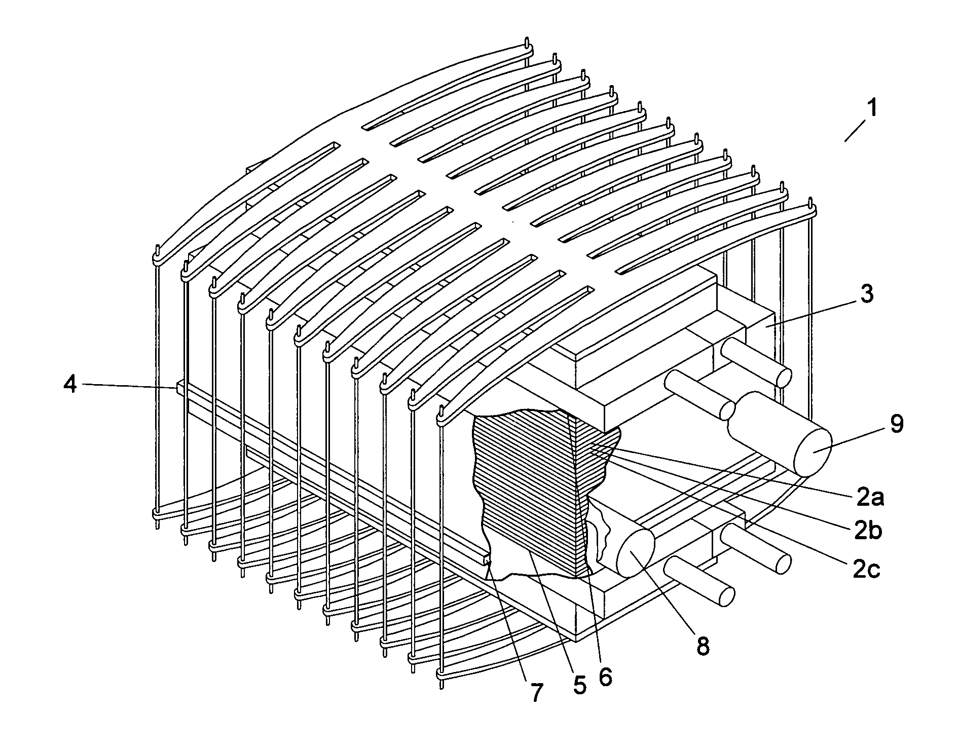
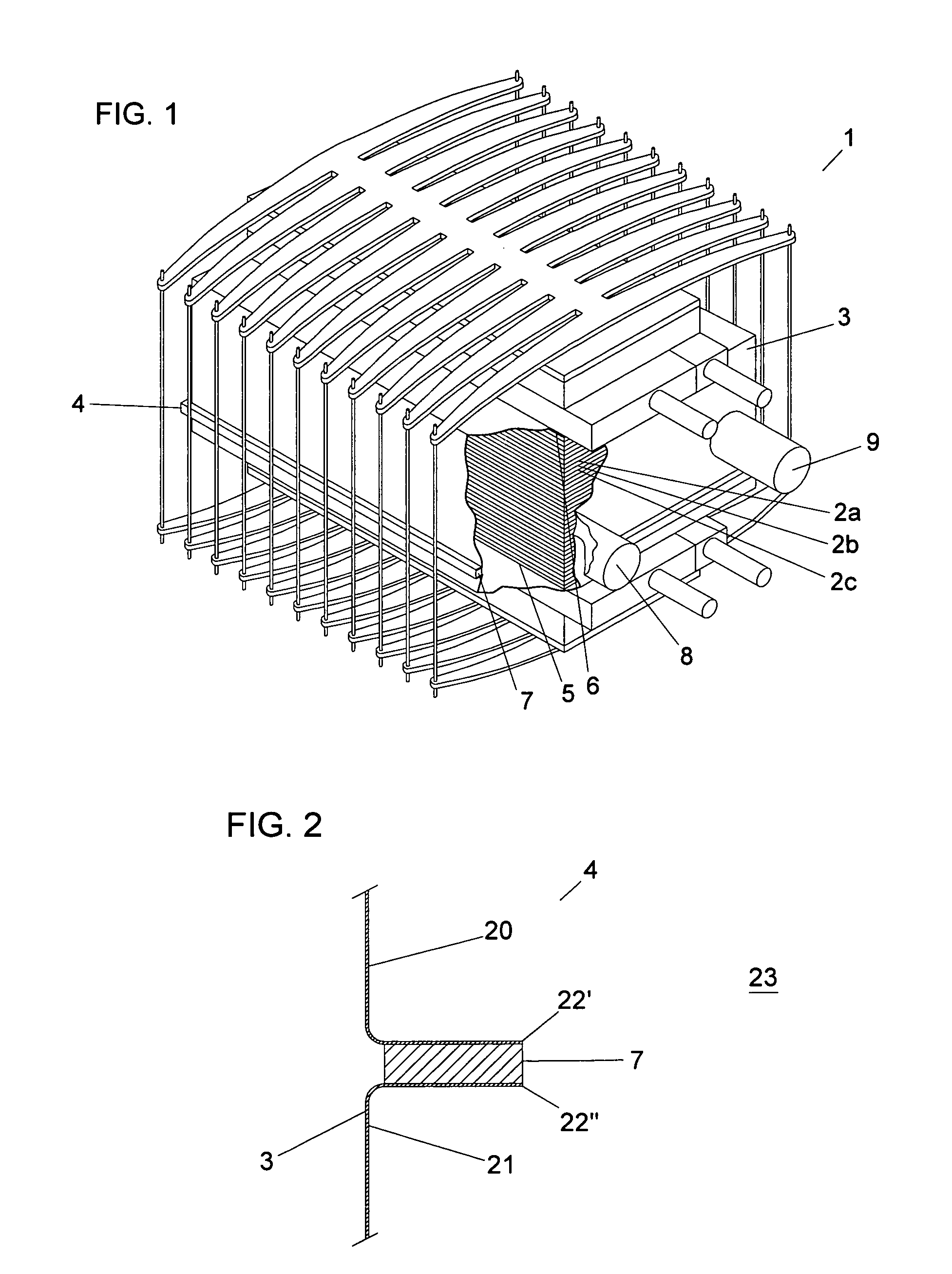
[0036]FIG. 1 illustrates a fuel cell stack 1 such as a fuel cell stack described in U.S. Pat. No. 6,670,069 hereby incorporated by reference in its entirety for all purposes. The fuel cell stack 1 includes a plurality of individual cells represented by 2a, 2b, 2c stacked upon one another. The fuel cell stack 1 is positioned within an enclosure 3 such that the fuel cell stack is substantially or entirely enclosed within the enclosure. Configurations and dimensions for enclosures are known to those of skill in the art and include those described in U.S. Pat. No. 6,670,069. The enclosure is configured to be in fluid communication with external inlet manifolds and external outlet manifolds of the plurality of individual fuel cells represented by 2a, 2b, 2c. As can be seen in FIG. 1, the enclosure is contacted by a compression assembly having an upper plate and a lower plate with the upper plate and lower plate being connected by plurality of fastening elements. Compression assemblies, i...


PUM


Abstract

Embodiments of the present invention are directed to fuel cell enclosures separate by a dielectric joint. The dielectric joint includes a flange portion from respective housing sections. A dielectric material is positioned between the respective flanges. Removable fasteners are used to secure the flanges and housing sections together.

Description

CROSS-REFERENCE TO RELATED APPLICATION(S) [0001] This application claims priority to U.S. Provisional Patent Application No. 60 / 655,990 filed Feb. 24, 2005 hereby incorporated by reference in its entirety for all purposes.FIELD OF THE INVENTION [0002] This invention relates to fuel cell stacks and in particular to methods for separating the positive pole of a fuel cell stack from the negative pole of the fuel cell stack using a dielectric material. BACKGROUND [0003] An electrochemical fuel cell converts the chemical bond energy potential of fuel to electrical energy in the form of direct current (DC) electricity. Fuel cells are presently being considered as replacement for battery storage systems and conventional electric generating equipment. [0004] An electrochemical fuel cell stack is formed of a plurality of individual fuel cells, each possessing a positive (+) and a negative (−) electrical pole, arranged in an electrical series relationship to produce higher useable DC voltage ...

Claims


Application Information

Patent Timeline
IPC IPC(8): H01M2/02
CPCH01M8/04082H01M8/2475H01M8/248H01M2008/147Y02E60/50Y02E60/526
Inventor BERNARD, RANDOLPH M.ALLEN, JEFFREY PETERALLEN, PETER WILCOX
Owner CONNECTICUT INNOVATIONS
Why Eureka
Try Eureka