Film-covered battery production method and film-covered battery

Active Publication Date: 2020-02-06
ENVISION AESC JAPAN LTD
View PDF1 Cites 1 Cited by
  • Summary
  • Abstract
  • Description
  • Claims
  • Application Information

AI Technical Summary

Benefits of technology

The patent improves the quality of sealing on the side of the casing that has electrode tabs.

Problems solved by technology

The result is that the conventional method of applying heat and / or pressure and thermally fusing both areas using the same heat block fails to always seal the areas under optimal conditions and leads to reduced sealing quality.

Method used


Image

  • Film-covered battery production method and film-covered battery
  • Film-covered battery production method and film-covered battery
  • Film-covered battery production method and film-covered battery

Examples


Embodiment Construction

[0025]Selected embodiment are described in detail below on the basis of the drawings.

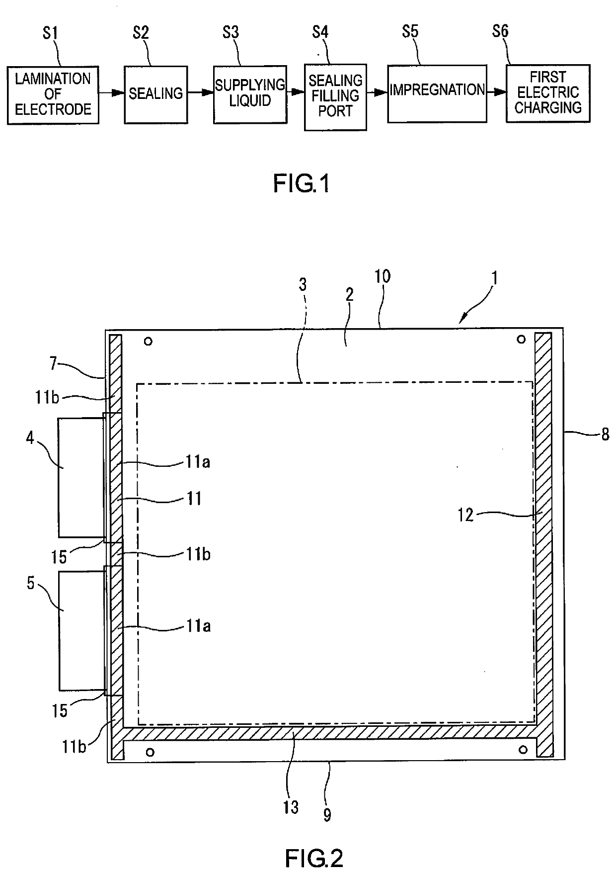
[0026]FIG. 1 is a process diagram illustrating the main steps of a method for producing a battery according to one embodiment. This embodiment considers a flat film-covered lithium ion secondary battery as a film-covered battery that constitutes part of a vehicle-driving power supply pack for an electric vehicle, a hybrid vehicle, or the like. The film-covered battery according to this working example is configured substantially identically to that disclosed in Japanese Laid-Open Patent Application No. 2013-140782, Japanese Laid-Open Patent Application No. 2015-37047, etc., and constitutes a power generation element (also referred to as a “layered electrode assembly”) obtained by layering a plurality of positive electrodes and negative electrodes configured as square sheets using an interposed separator. The power generation element is housed together with a liquid electrolyte in a bag-shaped casing...


PUM


Abstract

A method is performed to produce a film-covered battery in which electrode tabs extend out from joining surfaces on a first side of lamination films, in which a seal line is formed along the first side and traversing the electrode tabs. Pressure and / or heat is applied only to tab regions of the seal line using tab-region heat blocks, and then pressure and / or heat is applied only to non-tab regions using non-tab-region heat blocks.

Description

CROSS-REFERENCE TO RELATED APPLICATIONS[0001]This application is a U.S. national stage application of International Application No. PCT / JP2016 / 086681, filed on Dec. 9, 2016.BACKGROUNDTechnical Field[0002]This invention relates to a method for producing a film-covered battery so that a power generation element is housed together with a liquid electrolyte in a casing made of flexible lamination films, and in particular relates to an improvement in a sealing step in which the lamination films are thermally fused while electrode tabs that protrude from the power generation element are held by the lamination films on both sides.Background Information[0003]Flat film-covered batteries are known as examples of lithium ion secondary batteries. In a film-covered battery, a power generation element in which a plurality of positive electrodes and negative electrodes are layered with a separator interposed therebetween is housed together with a liquid electrolyte in a casing made of lamination f...

Claims


Application Information

Patent Timeline
IPC IPC(8): H01M2/36H01M2/02H01M2/08H01M50/105H01M50/178H01M50/186H01M50/636
CPCH01M2/0202H01M2/365H01M2/08H01M10/056Y02E60/10H01M50/105H01M50/186H01M50/178H01M50/124H01M50/557H01M50/55H01M50/531H01M50/129H01M50/119H01M50/121
Inventor YANAGI, TAKAHIRO
Owner ENVISION AESC JAPAN LTD
Why Eureka
Try Eureka