Decoration device, method for using light emitting device, and vehicle

a technology of light emitting devices and decoration devices, which is applied in the direction of semiconductor devices for light sources, lighting and heating apparatus, planar light sources, etc., can solve the problem of not quantitatively representing the visibility of objects, and achieve the effect of light transmittivity and flexibility

Pending Publication Date: 2021-07-08
NICHIA CORP
View PDF7 Cites 0 Cited by
  • Summary
  • Abstract
  • Description
  • Claims
  • Application Information

AI Technical Summary

Benefits of technology

[0007]In order to attain the object described above, a decoration device according to this embodiment is a decoration device decorating an object used indoors, including: a light emitting device having light transmittivity and flexibility, including a plurality of light emitting elements emitting light from one surface and the other surface, and being arranged on one side of the object, in which a distance between the object and the light emitting device when an indoor light is turned off is less than or equal to 90 cm.

Problems solved by technology

However, the visibility of the object has not been quantitatively represented.

Method used


Image

  • Decoration device, method for using light emitting device, and vehicle
  • Decoration device, method for using light emitting device, and vehicle
  • Decoration device, method for using light emitting device, and vehicle

Examples


Embodiment Construction

[0039]Hereinafter, one embodiment of the invention will be described by using the drawings. In the description, an XYZ coordinate system including an X axis, a Y axis, and a Z axis orthogonal to each other is used.

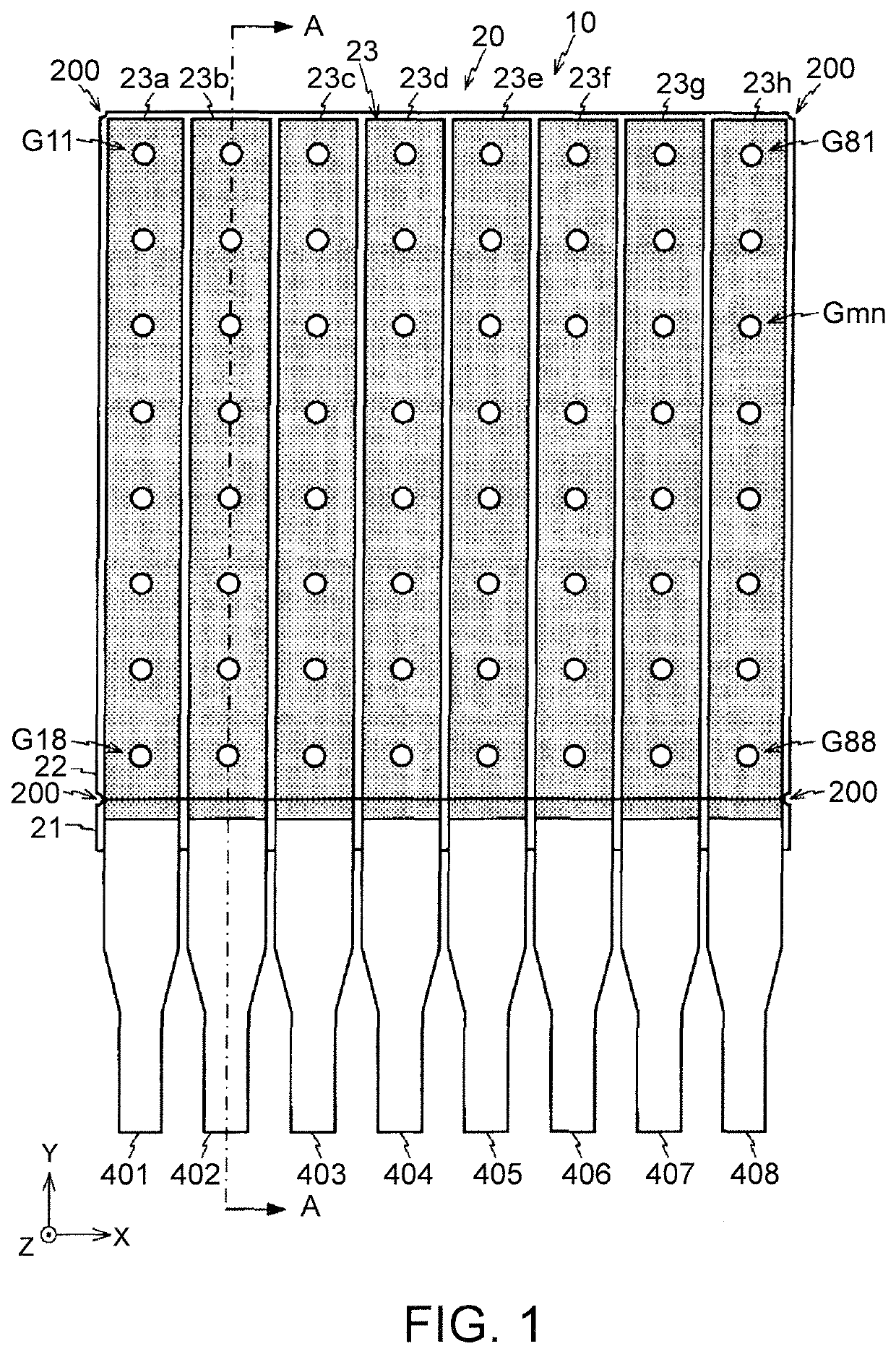
[0040]FIG. 1 is a plan view of a light emitting device 10 according to this embodiment. As illustrated in FIG. 1, the light emitting device 10 is a module in which a longitudinal direction is set to a Y axis direction. The light emitting device 10 includes a square light emitting panel 20, and eight flexible cables 401 to 408 that are connected to the light emitting panel 20.

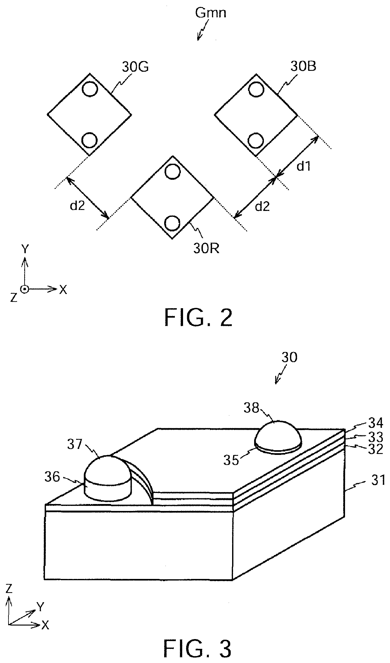
[0041]The light emitting panel 20 is a panel including 64 point light sources Gmn (=G11 to G88: m and n are an integer of 1 to 8) that are arranged into the shape of a matrix of eight rows and eight columns. The dimension of the light emitting panel 20 in an X axis direction and the Y axis direction is approximately 10 cm to 15 cm. FIG. 2 is a plan view illustrating the point light source Gmn. As illus...


PUM

PropertyMeasurementUnit
distanceaaaaaaaaaa
distanceaaaaaaaaaa
distanceaaaaaaaaaa

Abstract

A decoration device according to this embodiment is a decoration device decorating an object used indoors, including: a light emitting device having light transmittivity and flexibility, including a plurality of light emitting elements emitting light from one surface and the other surface, and being arranged on one side of the object, in which a distance between the object and the light emitting device when an indoor light is turned off is less than or equal to 90 cm.

Description

CROSS REFERENCE TO RELATED APPLICATION[0001]This application is a division of U.S. application Ser. No. 16 / 519,543, filed Jul. 23, 2019, the entirety of which is incorporated by reference.FIELD OF THE INVENTION[0002]An embodiment of the present invention relates to a decoration device, a method for using a light emitting device, and a vehicle.BACKGROUND OF THE INVENTION[0003]Recently, an effort for reducing energy consumption has been emphasized. From such a background, a light emitting diode (LED) having comparatively small power consumption has attracted attention as a next-generation light source. The LED has a small size and a small calorific value, and also has excellent responsiveness. For this reason, the LED has been widely used in various optical devices. For example, recently, a light emitting device including an LED arranged on a substrate having flexibility and translucency as a light source has been proposed.[0004]It has been known that in a case where an object positio...

Claims


Application Information

Patent Timeline
Patent Type & Authority Applications(United States)
IPC IPC(8): F21V19/00F21S43/14
CPCF21V19/0015F21Y2105/16F21S43/14F21S43/15F21S43/195F21S43/31F21S43/40F21Y2115/10
Inventor MATSUSHITA, KOICHIOOTAKE, TAKAMASA
Owner NICHIA CORP
Why Eureka
Try Eureka