Radar system for a vehicle

a technology for a radar system and a vehicle, applied in the direction of antenna details, instruments, antennas, etc., can solve the problems of high cost, complicated and complex solutions, and insufficiently meeting the requirements of conventional solutions, and achieve the effect of cost-effective and enlarged virtual apertur

Active Publication Date: 2021-07-22
HELLA KG HUECK & CO
View PDF23 Cites 0 Cited by
  • Summary
  • Abstract
  • Description
  • Claims
  • Application Information

AI Technical Summary

Benefits of technology

[0009]In particular, it is provided that all of the reception antennas are arranged at different distances from one another in the first direction, so that preferably only one of these distances corresponds to the minimum ambiguous range. This offers the advantage that the assignment and thus the determination of the viewing angles for different targets can be improved. In particular, the antenna arrangement having the transmission and reception antennas allows for the ambiguity to be distributed over more viewing angles.
[0034]Advantageously, it can be provided within the scope of the invention that the processing device is designed to perform a beamforming technique for the determination of the viewing angle. This enables a particularly efficient and fast determination of the viewing angles.

Problems solved by technology

In some cases, conventional solutions do not adequately meet these requirements.
In particular, such solutions may be technically complicated and complex, and therefore also associated with higher costs.

Method used


Image

  • Radar system for a vehicle
  • Radar system for a vehicle
  • Radar system for a vehicle

Examples


Embodiment Construction

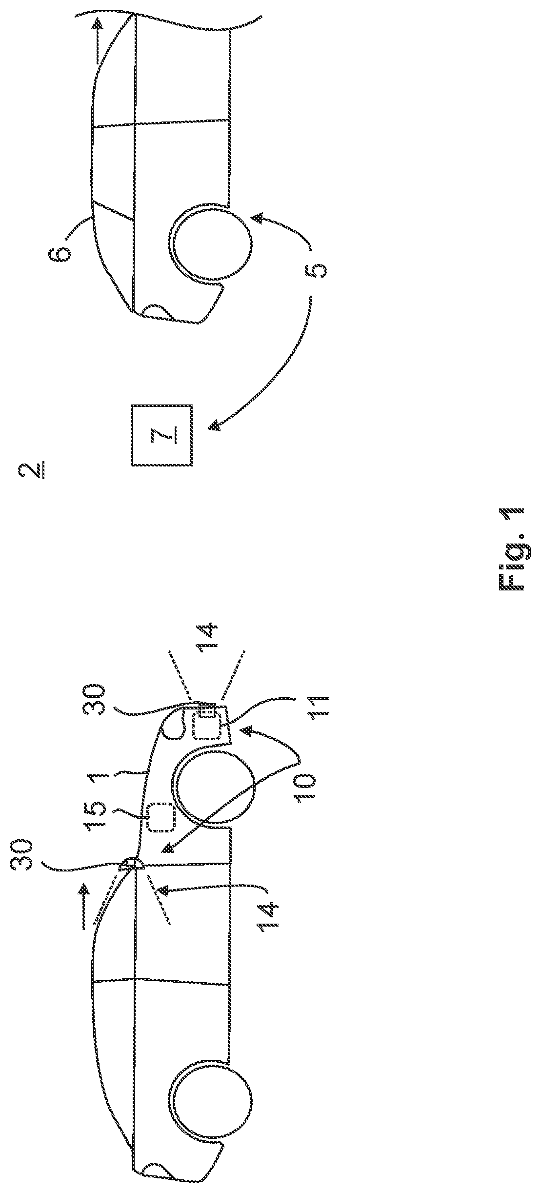
[0043]FIG. 1 schematically shows a vehicle 1 with a radar system 10 according to the invention. An arrow symbolizes the direction of movement of the vehicle 1. In addition, a moving object 6 in the form of another vehicle traveling ahead and a static object 7 in the surroundings 2 of the vehicle 1 are shown. The moving object and the static object are each objects 5 which are located in at least one detection field 14 of the radar system 10. By way of example, different detection fields 14 for different positions of at least one reception antenna 30 are shown in FIG. 1, which can be provided alternatively or in combination. Thus, the radar system 10 can be arranged at least partially in the exterior mirror or in the bumper or the like. A radar sensor 11, as a detector 11 depending on the position of the vehicle 1, can thereby receive reflections from these objects 5 via the at least one reception antenna 30 and detect the objects 5 and / or reconstruct the surroundings 2 on the basis ...


PUM


Abstract

A radar system for a vehicle, having at least two transmission antennas, each for emitting a transmission signal into the surroundings of the vehicle, at least four reception antennas, each for acquiring a detection signal for detecting targets in the surrounding of the vehicle, and a processing device for determining the viewing angle, in order to assign phase information in the detection signals to at least one viewing angle for respective detected targets, such that a minimum ambiguous range of the reception antennas in a first direction is specific for the assignment to be ambiguous to more than one viewing angle, wherein all of the reception antennas are spaced apart from each other in the first direction by different distances such that only one of the distances corresponds to the minimum ambiguous range.

Description

[0001]This nonprovisional application is a continuation of International Application No. PCT / EP2019 / 075717, which was filed on Sep. 24, 2019 and which claims priority to German Patent Application No. 10 2018 124 503.3, which was filed in Germany on Oct. 4, 2018 and which are both herein incorporated by reference.BACKGROUND OF THE INVENTIONField of the Invention[0002]The present invention relates to a radar system for a vehicle.Description of the Background Art[0003]The range of applications for radar sensors in the automotive industry continues to increase. Both long-range functions such as a highway pilot with ranges of up to 200 m, for example, and short-range applications such as automated parking can be supported.[0004]This places high demands on the measurement capability not only of the distance and the speed of targets, but also in relation to the angle of the targets. In far field applications, the focus is on azimuthal measurement capability. For example, it may be a requir...

Claims


Application Information

Patent Timeline
Patent Type & Authority Applications(United States)
IPC IPC(8): G01S13/42G01S7/03G01S13/931H01Q3/36
CPCG01S13/426G01S7/03G01S2013/9314H01Q3/36G01S13/931G01S13/42H01Q21/22H01Q3/24H01Q1/3233
Inventor AL KADI, MUHAMMED SOUBHIBREDDERMANN, TOBIASFARHOUD, RIDHAFEI, TAIGRIMM, CHRISTOPHERWARSITZ, ERNST
Owner HELLA KG HUECK & CO
Why Eureka
Try Eureka