
Wireless communication antenna structure for both heat dissipation and radiation

a technology of wireless communication and antenna structure, applied in the direction of radiating element structure, near-field system using receiver, transmission, etc., can solve the problem of thickening of the entire thickness, achieve the effect of maximizing the communication function, facilitating heat dissipation, and maximizing the near-field wireless communication performan

Active Publication Date: 2021-07-22
SHENZHEN ACCOMTECH COMM ELECTRONICS CO LTD
View PDF0 Cites 2 Cited by
  • Summary
  • Abstract
  • Description
  • Claims
  • Application Information

AI Technical Summary

Benefits of technology

This patent is about a new wireless communication antenna that can dissipate heat and improve communication performance. The antenna is made by patterning metal layers on a thin and flexible film, which can be wound by a heat dissipating / radiating metal layer on the other side of the film. This allows the antenna to maximize heat dissipation and improve wireless communication. The patent also describes a method for connecting the antenna to a portable terminal in a way that optimizes communication and heat dissipation. Overall, this invention provides a way to make a thin, light, and short portable terminal with high-quality communication and heat dissipation guarantees.

Problems solved by technology

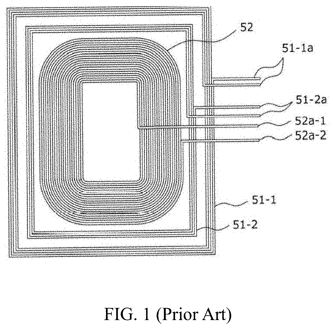
However, the structure of a wireless antenna coil of the prior art used in smart phones is composed of a structure of coating heat dissipating layer on the heat dissipating film 57 to form the heat dissipating layer 57a and forming the conductive adhesive layer 57b under the heat dissipating film 57 in order to bond other layers, thus, it may bring the problem that the entire thickness become thicker due to the thickness of the heat dissipating film 57.

Method used


Image

  • Wireless communication antenna structure for both heat dissipation and radiation
  • Wireless communication antenna structure for both heat dissipation and radiation
  • Wireless communication antenna structure for both heat dissipation and radiation

Examples


first embodiment

[0104]The wireless communication antenna for both heat dissipation and radiation of the present disclosure, as illustrated in FIG. 9a, may enable the inside helical pattern H10 and the outside helical pattern H20 to be formed on one side surface of the flexible film F in a manner of centering on the expanded slot S2 on the other side surface of the flexible film F and being arranged at an peripheral of the expanded slot S2 (most of paths of a magnetic field occurring due to currents of a near field transmitter are guaranteed through the expanded slot S2, so that a wireless communication antenna of a portable terminal is connected omni-directionally to form an induced current).

second embodiment

[0105]The wireless communication antenna for both heat dissipation and radiation of the present disclosure, as illustrated in FIG. 9b, may enable the inside helical pattern H10 and the outside helical pattern H20 to be formed on one side surface of the flexible film F in a manner of being hung on the expanded slot S2 on the other side surface of the flexible film F (through the expanded slot S2 and the one-way open slit S1, it may guarantee paths of a magnetic field occurring due to currents of a near field transmitter, so that a wireless communication antenna of a portable terminal is connected omni-directionally to form an induced current).

third embodiment

[0106]The wireless communication antenna for both heat dissipation and radiation of the present disclosure, as illustrated in FIG. 9c, may surely enable the inside helical pattern H10 and the outside helical pattern H20 to be formed on one side surface of the flexible film F in a manner of being hung on the one-way open slit S1 on the other side surface of the flexible film F (through the expanded slot and the one-way open slit, it may guarantee paths of a magnetic field occurring due to currents of a near field transmitter, so that a wireless communication antenna of a portable terminal is connected omni-directionally to form an induced current).


PUM


Abstract

The present disclosure provides a wireless communication antenna structure for both heat dissipation and radiation which includes: an inside helical pattern including an inside start end and an inside tail end; an outside helical pattern including an outside start end and an outside tail end; a heat dissipating / radiating metal layer including one side metal region and the other side metal region; and a plurality of via holes respectively connecting, up and down, the inside tail end and the one side metal region, and the outside start end and the other side metal region, so that the inside helical pattern, the heat dissipating / radiating metal layer and the outside helical pattern are connected in sequence to be a helical type. The present disclosure also implements heat dissipation of various components inside a portable terminal while implementing better near field wireless communication.

Description

TECHNICAL FIELD[0001]The present disclosure relates to a wireless communication antenna structure for both heat dissipation and radiation, and in particular, relates to a wireless communication antenna that reflects an inside helical pattern, a heat dissipating / radiating metal layer and an outside helical pattern connected in sequence in a helical type by using a metal layer at one side surface and a metal layer at the other side surface of a thin and soft flexible film. That is, a helical-type wireless communication antenna not only having the inside helical pattern and the outside helical pattern on the one surface of the flexible film, but also being wound by means of the additional number of turns of the heat dissipating / radiating metal layer on the one surface of the flexible film enables the heat dissipating / radiating metal layer to work as a radiating body. On this account, while enabling the performance of near field wireless communication to be further maximized, as a heat ...

Claims


Application Information

Patent Timeline
Patent Type & Authority Applications(United States)
IPC IPC(8): H01Q1/02H01Q1/36H01Q1/38
CPCH01Q1/02H01Q1/38H01Q1/362H01Q7/00H04B5/72H04B5/26H04B5/79H04B5/48H04B5/43
Inventor GUO, TIENANGUO, TIELONGXU, GUANGLINTAN, YONGGANG
Owner SHENZHEN ACCOMTECH COMM ELECTRONICS CO LTD
Learn More