Vehicle display device

a technology for displaying devices and vehicles, applied in navigation instruments, instruments, transportation and packaging, etc., can solve the problems of unrealistic and difficult to construct the optical system for realizing such a large head-up display

Active Publication Date: 2021-07-29
TOYOTA JIDOSHA KK
View PDF2 Cites 0 Cited by
  • Summary
  • Abstract
  • Description
  • Claims
  • Application Information

AI Technical Summary

Benefits of technology

[0005]The present disclosure has been devised in consideration of the above circumstances and provides a vehicle display device which, even in the case of displaying information on a small display unit that does not widely cover the forward field of view of an occupant, allows the occupant to intuitively grasp that the display information corresponds to the actual foreground.
[0007]In the aspect, the display control unit moves the display positions, on the display unit, of the markers that is displayed in positions on the display unit corresponding to the future positions of the host vehicle, toward the reference position on the display unit corresponding to the host vehicle, in accordance with the travel of the host vehicle. Because of this, the display positions of the markers move as if synchronously with the travel of the host vehicle, so even in the case of displaying information on a small display unit that does not cover the forward field of view of the occupant, the display control unit allows the occupant to intuitively grasp that the display information corresponds to the actual foreground. Furthermore, the dynamic flow of the markers serves as an appropriate stimulant and helps the occupant maintain the motivation to continuously monitor the travel of the host vehicle.
[0009]The moving of the display positions of the markers on the display unit toward the reference position on the display unit may be realized by switching the future positions at which the display control unit displays the markers so that the time differences of the future positions from the current time become smaller as time elapses as described above for example. Because of this, the display positions of the markers on the display unit may be moved by the simple process of switching the future positions at which the display control unit displays the markers.
[0011]In this configuration, the time differences, from the current time, of the plural future positions at which the display control unit displays the markers differ a predetermined amount of time each. Therefore, the display control unit allows the occupant to intuitively grasp, from the display intervals between the plural markers, changes in the behavior of the host vehicle in the time axis direction including acceleration and deceleration of the host vehicle.
[0013]In this configuration, the display control unit displays the band-like trajectory line, and the trajectory line has its width direction aligned with the vehicle width direction of the host vehicle, has its length direction aligned with the array of future positions of the host vehicle, and contains the markers. Therefore, it allows the occupant to intuitively grasp, from the direction in which the trajectory line extends, the advancing position of the host vehicle.
[0019]In this configuration, the display unit is a small display that does not widely cover the forward field of view of the occupant, namely, a head-up display whose display range is part of the forward field of view of the occupant of the host vehicle or a display provided in the instrument panel of the host vehicle. Because of this, the vehicle display device may employ a configuration that is easy to implement as the display unit and allows the occupant to intuitively grasp that the information displayed on the display corresponds to the actual foreground.

Problems solved by technology

H08-178679 presupposes displaying information on a superimposed (augmented reality, or AR) type head-up display that entirely covers the forward field of view of an occupant in the front seat of the vehicle, but the optical system for realizing such a large head-up display is extremely difficult to construct and at the present time is not realistic.

Method used


Image

  • Vehicle display device
  • Vehicle display device
  • Vehicle display device

Examples


Embodiment Construction

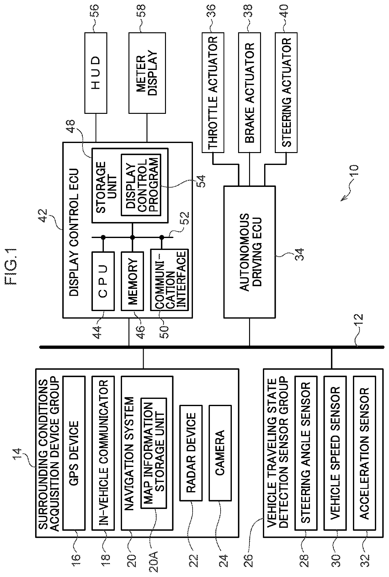
[0038]An exemplary embodiment of the disclosure will be described in detail below with reference to the drawings. An in-vehicle system 10 illustrated in FIG. 1 is equipped with a communication bus 12, and connected to the communication bus 12 are a surrounding conditions acquisition device group 14, a vehicle traveling state detection sensor group 26, an autonomous driving electronic control unit (ECU) 34, and a display control ECU 42. It will be noted that FIG. 1 illustrates only part of the in-vehicle system 10. Furthermore, below, the vehicle in which the in-vehicle system 10 is installed is called the host vehicle.

[0039]The surrounding conditions acquisition device group 14 includes, as devices that acquire information about the conditions of the environment around the host vehicle, a global positioning system (GPS) device 16, an in-vehicle communicator 18, a navigation system 20, a radar device 22, and a camera 24.

[0040]The GPS device 16 receives GPS signals from plural GPS sat...


PUM


Abstract

A vehicle display device includes a display control unit that is configured to: display markers in positions, on a display unit, corresponding to future positions of a host vehicle which are acquired from an autonomous driving control unit that autonomously drives the host vehicle, and move display positions of the markers on the display unit in accordance with travel of the host vehicle and toward a reference position on the display unit corresponding to the host vehicle.

Description

CROSS-REFERENCE TO RELATED APPLICATION[0001]This is a continuation application of U.S. patent application Ser. No. 16 / 831,230, filed Mar. 26, 2020, which is based on and claims priority under 35 USC 119 from Japanese Patent Application No. 2019-064664 filed on Mar. 28, 2019, the disclosures of which are incorporated by reference herein.BACKGROUNDTechnical Field[0002]The present disclosure relates to a vehicle display device.Related Art[0003]Japanese Patent Application Laid-open (JP-A) No. H08-178679 discloses a technology that detects the traveling state of a vehicle, calculates a future projected trajectory of the vehicle on the basis of the detected traveling state, and displays the projected trajectory on a head-up display device. In this technology, the projected trajectory is displayed as a bird's eye view in which a group of points are arrayed at predetermined intervals on a curve representing the projected trajectory of the center of gravity of the vehicle and in which boxes ...

Claims


Application Information

Patent Timeline
Patent Type & Authority Applications(United States)
IPC IPC(8): G01C21/36B60K35/00B60W30/095
CPCG01C21/365G01C21/3658B60W30/0956B60K35/00G02B27/0101G02B2027/0141G02B2027/014B60K2370/166B60K2370/178B60K2370/176B60K2370/177B60K2370/1529B60W60/00B60W50/14B60W2050/146B60W50/0097
Inventor KUMON, HITOSHI
Owner TOYOTA JIDOSHA KK
Why Eureka
Try Eureka