Check patentability & draft patents in minutes with Patsnap Eureka AI!

Time-domain reflectometry matrix suction sensor

a matrix suction sensor and reflectometry technology, applied in the field of soil science and hydrology, can solve the problems of affecting the reading, making it harder for plants to extract more water,

Active Publication Date: 2021-07-29
SKALING WHITNEY
View PDF0 Cites 1 Cited by
  • Summary
  • Abstract
  • Description
  • Claims
  • Application Information

AI Technical Summary

Benefits of technology

The patent describes a sensor and a method for measuring the suction exhibited by a porous medium using a TDR matrix suction sensor. The sensor includes conductors and a jacket made of a hydrophilic, non-conductive material. The sensor is placed within the porous medium and an initial electrical pulse is injected into the conductors. The time it takes for the reflected pulse to reach the detector is recorded and a pulse delay time is computed. The sensor's jacket material is then used to compute the matrix suction exhibited by the porous medium based on the pulse delay time and a delay-to-matrix suction profile. This allows for the measurement of the suction exhibited by the porous medium. The sensor can be used in various applications such as oil drilling and environmental monitoring.

Problems solved by technology

Thus, it becomes harder and harder for the plant to extract more water.
Regardless of how the jacket is formed, the resulting structure has interior cavities that accommodate the conductors and conform to the shape of the conductors, such that the walls of each jacket cavity contacts a conductor across its exterior surface without forming any significant gaps where liquid could pool (thereby adversely affecting the readings).
However, even though a TDR matrix suction sensor can employ parts of an existing TDR sensor, they operate differently.

Method used


Image

  • Time-domain reflectometry matrix suction sensor
  • Time-domain reflectometry matrix suction sensor
  • Time-domain reflectometry matrix suction sensor

Examples


Embodiment Construction

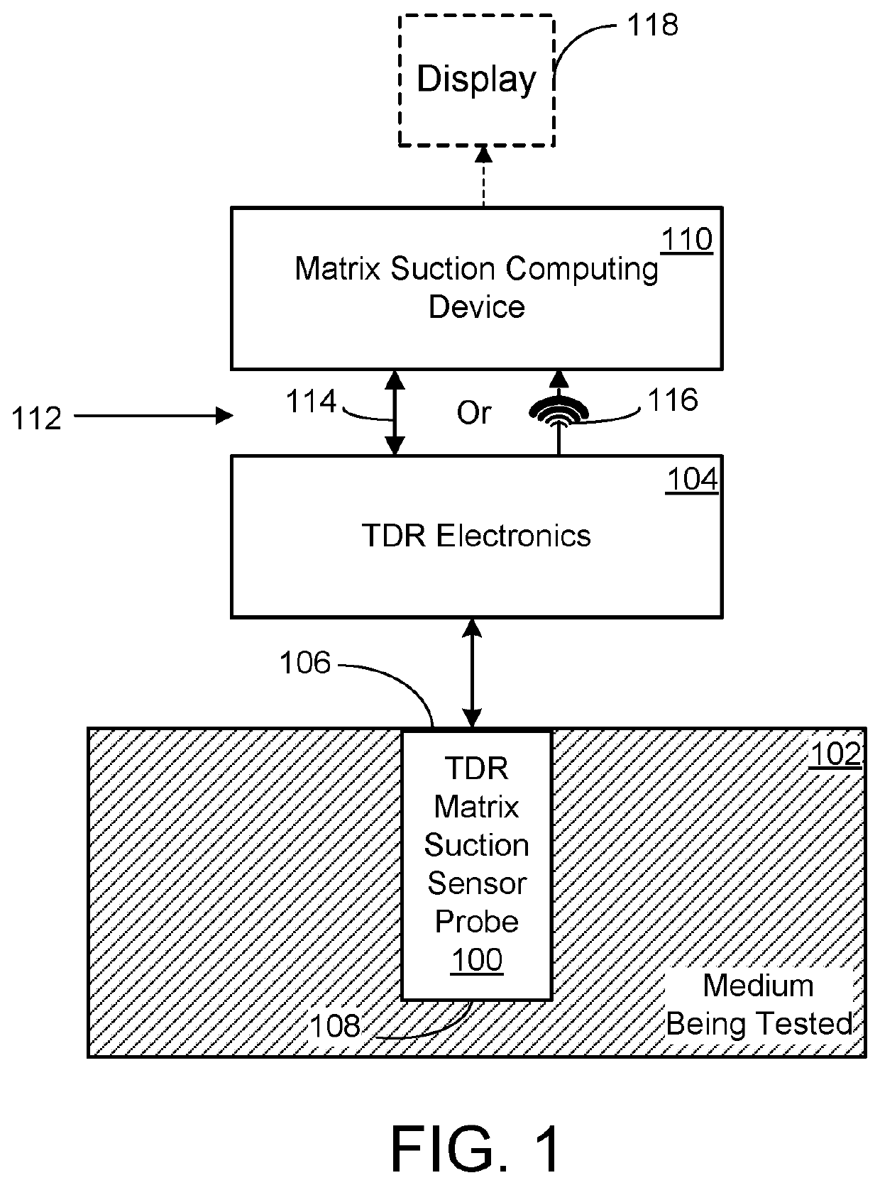
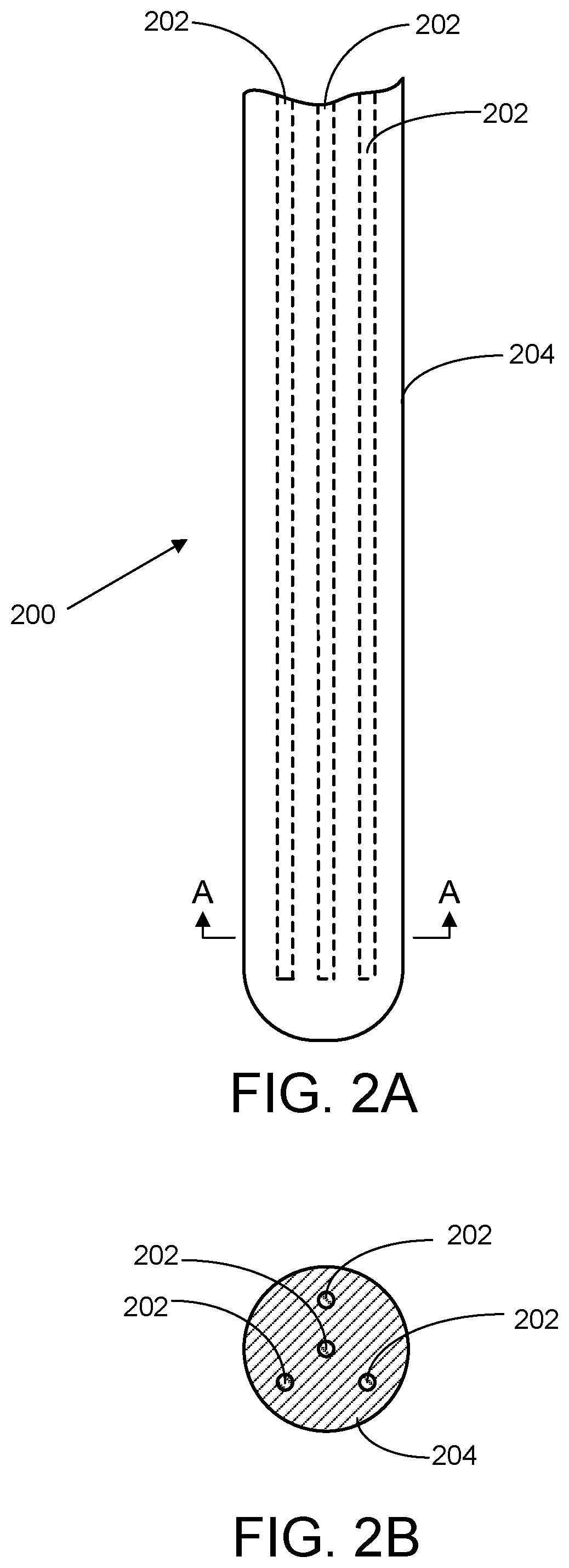
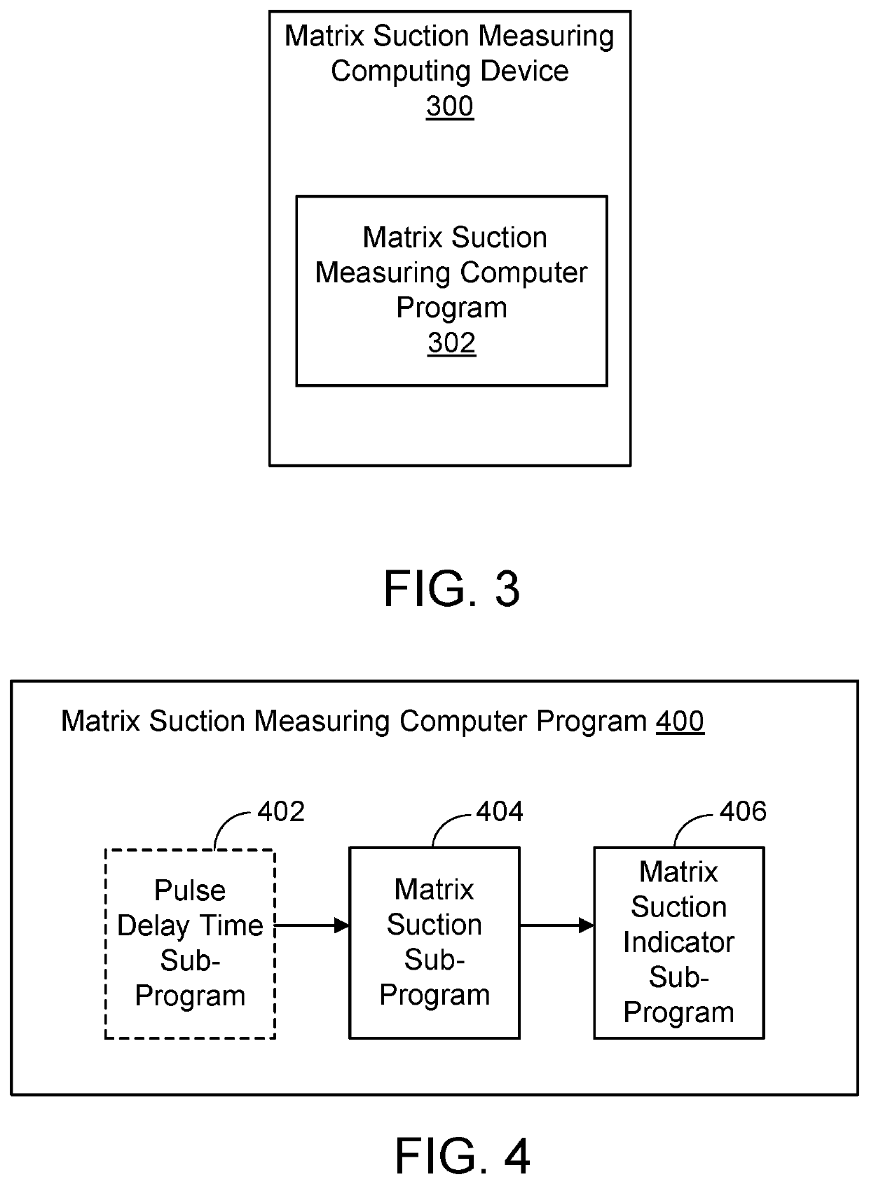
[0015]In the following description reference is made to the accompanying drawings which form a part hereof, and in which are shown, by way of illustration, specific implementations in which a TDR matrix suction sensor can be practiced. It is understood that other implementations can be utilized and structural changes can be made without departing from the scope of the TDR matrix suction sensor.

[0016]It is also noted that for the sake of clarity specific terminology will be resorted to in describing the TDR matrix suction sensor implementations described herein and it is not intended for these implementations to be limited to the specific terms so chosen. Furthermore, it is to be understood that each specific term includes all its technical equivalents that operate in a broadly similar manner to achieve a similar purpose. Reference herein to “one implementation”, or “another implementation”, or an “exemplary implementation”, or an “alternate implementation”, or “some implementations”...


PUM

PropertyMeasurementUnit
time-aaaaaaaaaa
matrix suctionaaaaaaaaaa
hydrophilicaaaaaaaaaa

Abstract

A TDR matrix suction sensor measures the matrix suction exhibited by a porous medium surrounding the sensor. The sensor is constructed from a TDR matrix suction sensor probe, which includes two or more elongated conductors and a jacket that encases the conductors. The jacket is made of a hydrophilic, non-conductive, porous (HN-CP) material. In operation, a pulse delay time is computed for an electrical pulse injected into the proximal end of the conductors and reflected when reaching their distal ends. The pulse delay time and a delay-to-matrix suction profile of the HN-CP jacket material are used to compute the matrix suction exhibited by the probe jackets. An indicator of the current value of the matrix suction exhibited by the porous medium is then established based on the matrix suction computed for the HN-CP jackets.

Description

BACKGROUND[0001]In the arts of soil science and hydrology, the hydraulic properties of various porous media are measured. Time-domain reflectometry (TDR) is a measurement technique which is used to measure a porous medium of interest. A TDR system generally includes a sensor which is disposed in the medium being tested and used to take the measurements. The measurements are then employed to determine the current properties of the media and optionally to monitor the media on an ongoing basis to detect changes in its properties. The media can be tested in situ (e.g., sensors can be disposed at different locations in a yard, farm field, process facility, or the like) or a sample of the media can be taken (such as a core sample and the like) and subsequently tested in a different setting such as a laboratory environment or the like.[0002]The term “porous medium” refers to a medium which is composed of solids such as minerals and organic compositions, air and / or other gases, and one or m...

Claims


Application Information

Patent Timeline
Patent Type & Authority Applications(United States)
IPC IPC(8): G01N13/04
CPCG01N13/04G01N13/00G01N22/04G01N33/246
Inventor SKALING, WHITNEY
Owner SKALING WHITNEY
Features
  • R&D
  • Intellectual Property
  • Life Sciences
  • Materials
  • Tech Scout
  • Unparalleled Data Quality
  • Higher Quality Content
  • 60% Fewer Hallucinations
Learn More