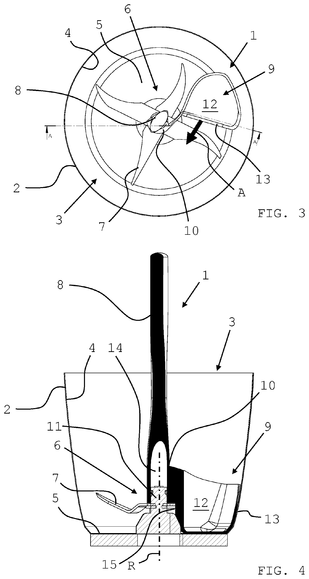
While the former can have a bowl with virtually completely smooth inner walls, this is not the case with the latter due to its design, since a
bushing for the mixing unit is needed which typically is located in the centre of the bottom of the bowl.
Usage of spoons, scoops or the same also results in comparably large amounts of mix remaining in the bowl.
The usage of spatulas of the described type is problematic in particular with regard to bowls that have a stirring unit which is located at the bottom, inasmuch as the unit impedes the scraping guiding of the spatula along the bottom area.
As a result, mix remains in the region of the stirring unit, which is undesired.
Further, sharp-edged parts of the stirring unit can damage the working element of the spatula, which is preferably, as mentioned, made from soft material in order to adapt to the different contours of the inner region of the bowl (side, transition region, bottom).
Insofar, the working result (speed, thoroughness) of using a spatula depends on the actual user, which is a
disadvantage.
However, usage of a shield is impractical with regard to common stirring bowls having a very large opening, since the shield would have to be very large as well.
Further, the proposed spatula does not solve the problem of removing mix adhering to region of the stirring unit.
Also, the spatula fails at removing liquid mix.
In the case of particularly liquid mix, the spatula is hardly
usable, since the mix which is already taken up by the spatula's edge and is pushed onto the spatula area quickly drops off the spatula again; a satisfying work result can only be achieved by a very fast or a very frequent repetition of the work motion.
In fact, such a mix can be removed more easily by means of a scoop; however, because of its bulky shape, even more mix remains in the poorly accessible region below the stirring unit and the transition region between inner wall and bottom area, in particular, when the transition region has a very small or very large
radius.
Further, also in case of a scoop, damages can occur due to, or of, the stirring unit.
Particularly critical is a situation in which an unintended operation of the rotating components of the stirring unit occurs.
Damage to the spatula or scoop as well as to the stirring unit can hardly be avoided.
Also, the user can injure himself with the suddenly rotating
handle.
But even when the stirring unit stands still, the manual removing of mix rests, often exercised with the fingers, from the poorly accessible region of the stirring unit can result in injuries from sharp-edged parts thereof.
However, by means of such a spatula it is impossible to get at the bottom of the vessel.
Furthermore, this spatula also fails during the removal of a liquid mix.

