Humeral Head Trial with Flexure

a technology of humeral head and flexure, which is applied in the field of humeral head trial with flexure, can solve the problems of preventing the trial from being attached and detachable to and from the implant, requiring significant extraction force, and affecting so as to achieve the effect of reducing preventing the risk of fracture, and reducing the sizing of the implan

Active Publication Date: 2021-08-19
HOWMEDICA OSTEONICS CORP
View PDF0 Cites 2 Cited by
  • Summary
  • Abstract
  • Description
  • Claims
  • Application Information

AI Technical Summary

Benefits of technology

[0010]Continuing in accordance with this aspect, the humeral head trial may be adapted to be secured to a humeral stem when the post is in an opening of the humeral stem in the first configuration such that a locking member on the post is secured in a corresponding recess in the opening. The first portion, the movable surface, the second portion, and the post may be integrally formed.
[0011]In a further aspect of the present disclosure, a humeral trialing system is provided. A humeral trialing system according to this aspect, may include a humeral head trial and a humeral stem. The humeral head trial may include a first portion, a second portion, and a post extending from the second portion. The first portion may define a concave articular surface. The concave articular surface may include a movable surface substantially flush with the concave articular surface. The second portion may define a flat surface. The post may define a first length in a first configuration and a second length in a second configuration. The first length may be greater than the second length. The post may change from the first configuration to the second configuration by moving the movable surface. The humeral stem may have an opening. The humeral head trial may be adapted to be secured to the humeral stem when the post is in the opening of the humeral stem in the first configuration. The first length may be the equal to or larger than an opening length such that the post forms an interference fit with the opening in the first configuration.
[0012]Continuing

Problems solved by technology

However, firmly securing a trial to the implant may prevent ready attachment and detachment of the trial to and from the implant.
Further, removing a firmly secured trial from an implant may require significant extraction forces which may be transferred to the implant during removal.
In such solutions there

Method used


Image

  • Humeral Head Trial with Flexure
  • Humeral Head Trial with Flexure
  • Humeral Head Trial with Flexure

Examples


Embodiment Construction

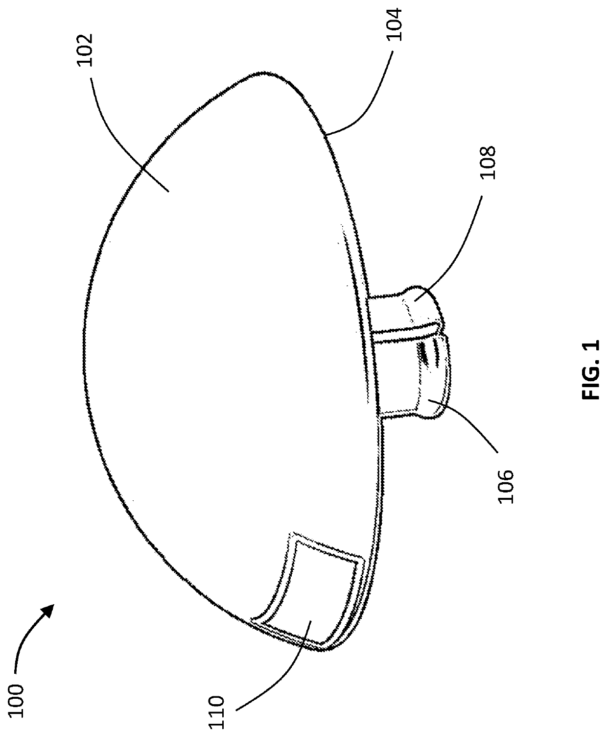
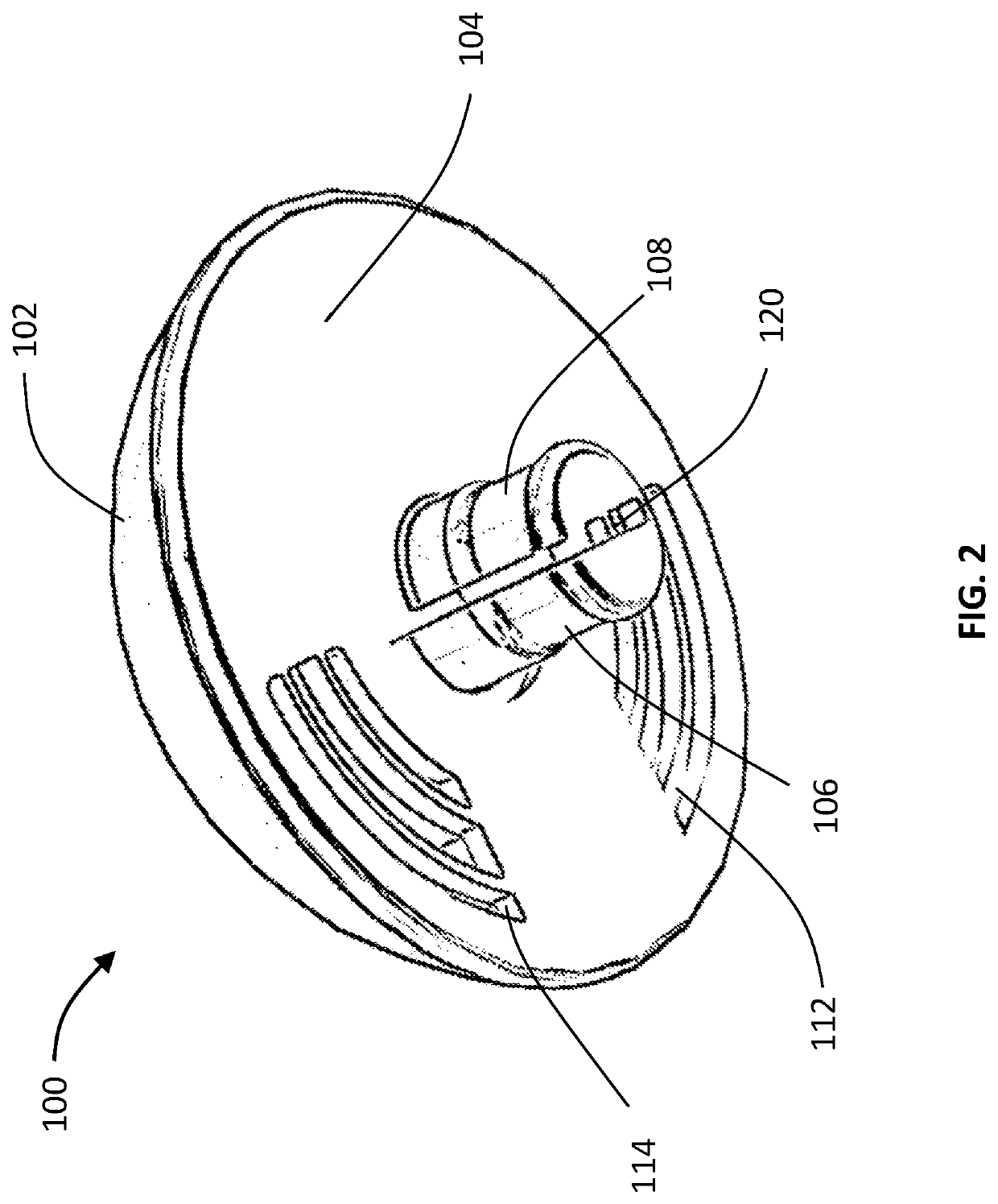
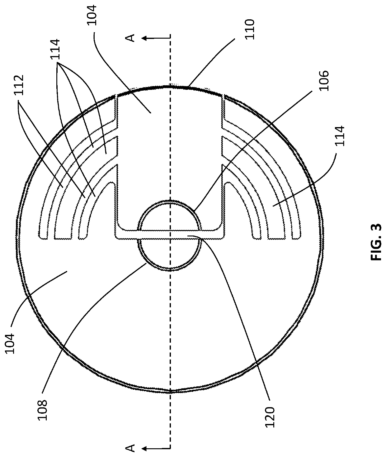
[0027]Reference will now be made in detail to the various embodiments of the present disclosure illustrated in the accompanying drawings. Wherever possible, the same or like reference numbers will be used throughout the drawings to refer to the same or like features. It should be noted that the drawings are in simplified form and are not drawn to precise scale. Additionally, the term “a,” as used in the specification, means “at least one.” The terminology includes the words above specifically mentioned, derivatives thereof, and words of similar import. Although at least two variations are described herein, other variations may include aspects described herein combined in any suitable manner having combinations of all or some of the aspects described. As used herein, the terms “implant trial” and “trial” will be used interchangeably and as such, unless otherwise stated, the explicit use of either term is inclusive of the other term. Similarly, the terms “implant” and “prosthesis” wil...


PUM


Abstract

Disclosed herein is a humeral head trial, a system for humeral trialing, and a method for removing a humeral head trial from a humeral stem. The humeral head trial may include a first portion, a second portion, and a post extending from the second portion. The first portion may define a concave articular surface with a movable surface substantially flush with the concave articular surface. The post may define a first length in a first configuration and a second length in a second configuration. The first length may be greater than the second length. The post may change from the first configuration to the second configuration by moving the movable surface with respect to the concave articular surface.

Description

CROSS-REFERENCE TO RELATED APPLICATIONS[0001]The present application claims the benefit of the filing of U.S. Provisional Patent Application No. 62 / 978,398, filed Feb. 19, 2020, the disclosure of which is hereby incorporated herein by reference.FIELD OF THE DISCLOSURE[0002]The present disclosure relates generally to an apparatus and a method of sizing implants, and in particular relates to a trial and a method for using a trial for implant sizing.BACKGROUND OF THE DISCLOSURE[0003]In an orthopedic joint replacement procedure, a surgeon may use a trial that is representative of a prosthesis or implant to assess the placement and size of the prosthesis or implant prior to implantation. In some instances, the trial preferably is secured firmly on an implant to allow for articulation of a patient's joint with the trial secured to the implant in order to evaluate the trial, and thus the prosthesis or implant represented by the trial. However, firmly securing a trial to the implant may pre...

Claims


Application Information

Patent Timeline
IPC IPC(8): A61F2/40A61F2/46
CPCA61F2/4014A61F2002/4029A61F2/4684A61F2002/4051A61F2002/30354A61F2002/30357A61F2002/30505
Inventor NELSON, ANDREW J.
Owner HOWMEDICA OSTEONICS CORP
Why Eureka
Try Eureka