Grabbing Device

a technology of grabbing device and grabbing head, which is applied in the direction of manipulators, gripping heads, manufacturing tools, etc., can solve problems such as damage to the surface of objects, and achieve the effect of good gripping

a technology of grabbing device and grabbing head, which is applied in the direction of manipulators, gripping heads, manufacturing tools, etc., can solve problems such as damage to the surface of objects, and achieve the effect of good gripping

US20210252719A1Active Publication Date: 2021-08-19SUZHOU DITIAN ROBOT & AUTOMATION CO LTD

Image

  • Grabbing Device
  • Grabbing Device

Examples


Embodiment Construction

[0026]In the following, the technical solution of the present disclosure is further described in view of the accompanying drawings.

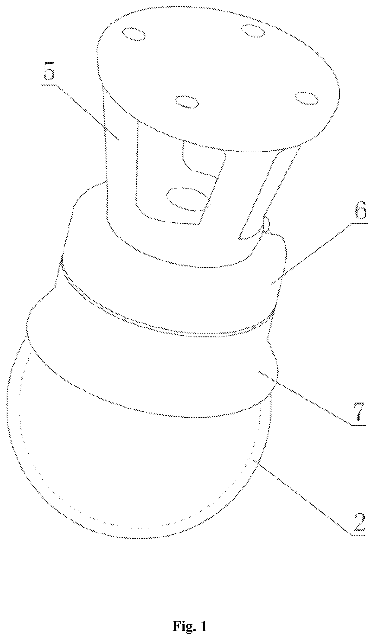
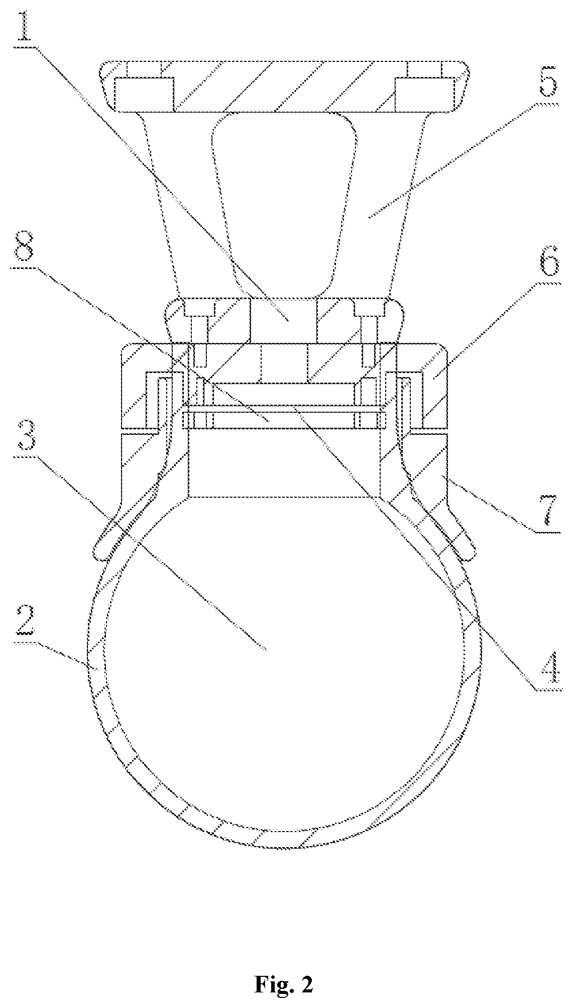
[0027]Referring to FIGS. 1-2, a grabbing device for grabbing an object, comprises a connection base for connecting a mechanical arm. The mechanical arm controls actions such as rising, falling, forwarding, backwarding, rotating, etc., of the connection base.

[0028]The above grabbing device further comprises a gas pipeline 1 provided in the connection base, a grabbing member 2 having a hollow cavity 3 and connected to the connection base, a filter layer 4 provided between the hollow cavity 3 and the gas pipeline 1, and particles filled in the hollow cavity 3 and capable of flow in the hollow cavity 3. The gas pipeline 1 is in communication with the hollow cavity 3 by the filter layer 4, and the filter layer 4 is used for preventing the particles from being suctioned into the gas pipeline 1. The hollow cavity 3 is inflated or deflated via the gas pipeline 1...


PUM


Abstract

A grabbing device, comprising a connection base, a gas pipeline provided in the connection base, a grabbing member having a hollow cavity and connected to the connection base, a filter layer provided between the hollow cavity and the gas pipeline, and particles filled in the hollow cavity. The gas pipeline is in communication with the hollow cavity by the filter layer for preventing the particles from entering the gas pipeline. The grabbing member is made of a flexible material, permitting the grabbing member to bulge when being inflated, and being recessed according to a shape of a surface of the object after the grabbing member contacts the object. The particles maintain the flexible state when the grabbing member is inflated, and the particles are pressed to the rigid state when withdrawing gas to deflate the grabbing member into a recessed position. The grabbing device can maintain a grip on objects having an irregular shape.

Description

CROSS REFERENCE TO RELATED APPLICATIONS[0001]This application claims the benefit of CN 201811019336.7 filed Sep. 3, 2018. That application is titled “Grabbing Device.”[0002]This application also claims the benefit of PCT / CN2019 / 083130 filed Apr. 18, 2018. That application is titled “Grabbing Device.”[0003]Each of these applications in incorporated herein in its entirety by reference.STATEMENT REGARDING FEDERALLY SPONSORED RESEARCH OR DEVELOPMENT[0004]Not applicable.THE NAMES OF THE PARTIES TO A JOINT RESEARCH AGREEMENT[0005]Not applicable.BACKGROUND OF THE INVENTION[0006]This section is intended to introduce various aspects of the art, which may be associated with exemplary embodiments of the present disclosure. This discussion is believed to assist in providing a framework to facilitate a better understanding of particular aspects of the present disclosure. Accordingly, it should be understood that this section should be read in this light, and not necessarily as admissions of prio...

Claims


Application Information

Patent Timeline
19 Aug 2021
Publication
US20210252719A1
IPC
B25J15/00
CPC
B25J15/0023; B25J15/0033
Inventors
WAN, XINFEI; KAI, WENZHONG