Aerofoil assembly and method

a technology of aerofoil and assembly, which is applied in the direction of blade accessories, engine control, machine/engine, etc., can solve the problems of large mixing loss, horseshoe vortices, and the purge air escape of conventional gas turbine engines, so as to reduce the loss of aerofoil and improve the stage efficiency of the turbine, the effect of reducing the weight of the turbin

Active Publication Date: 2021-09-02
ROLLS ROYCE PLC
View PDF0 Cites 0 Cited by
  • Summary
  • Abstract
  • Description
  • Claims
  • Application Information

AI Technical Summary

Benefits of technology

[0007]The recesses may provide an easier escape path for purge air to leak into a hot gas region with minimal interaction with the leading edges. Maintaining a gap or distance between a flow of purge air and the leading edges may mitigate the formation of pressure side horseshoe vortices. Therefore, the recesses may reduce secondary losses in a passage between adjacent aerofoils. Consequently, the recesses may improve an efficiency of the aerofoil assembly. Further, the recesses may result in weight reduction of the aerofoil assembly.
[0029]The method may improve the stage efficiency of a turbine by mitigating the formation of pressure side horseshoe vortices. The method may also result in weight reduction of the turbine.

Problems solved by technology

Nevertheless, conventional gas turbine engines exhibit a significant amount of purge air escape into the hot gas path.
The consequent mixing of cooler purge air with hot gas results in large mixing losses, due not only to the differences in temperature but also due to the differences in flow direction or swirl of purge air and hot gases.
Losses may also result from the formation of strong pressure side horseshoe vortices.
Such losses may decrease the efficiency of the gas turbine engine.
Further, the recesses may result in weight reduction of the aerofoil assembly.
The method may also result in weight reduction of the turbine.

Method used


Image

  • Aerofoil assembly and method
  • Aerofoil assembly and method
  • Aerofoil assembly and method

Examples


Embodiment Construction

[0079]Aspects and embodiments of the present disclosure will now be discussed with reference to the accompanying figures. Further aspects and embodiments will be apparent to those skilled in the art.

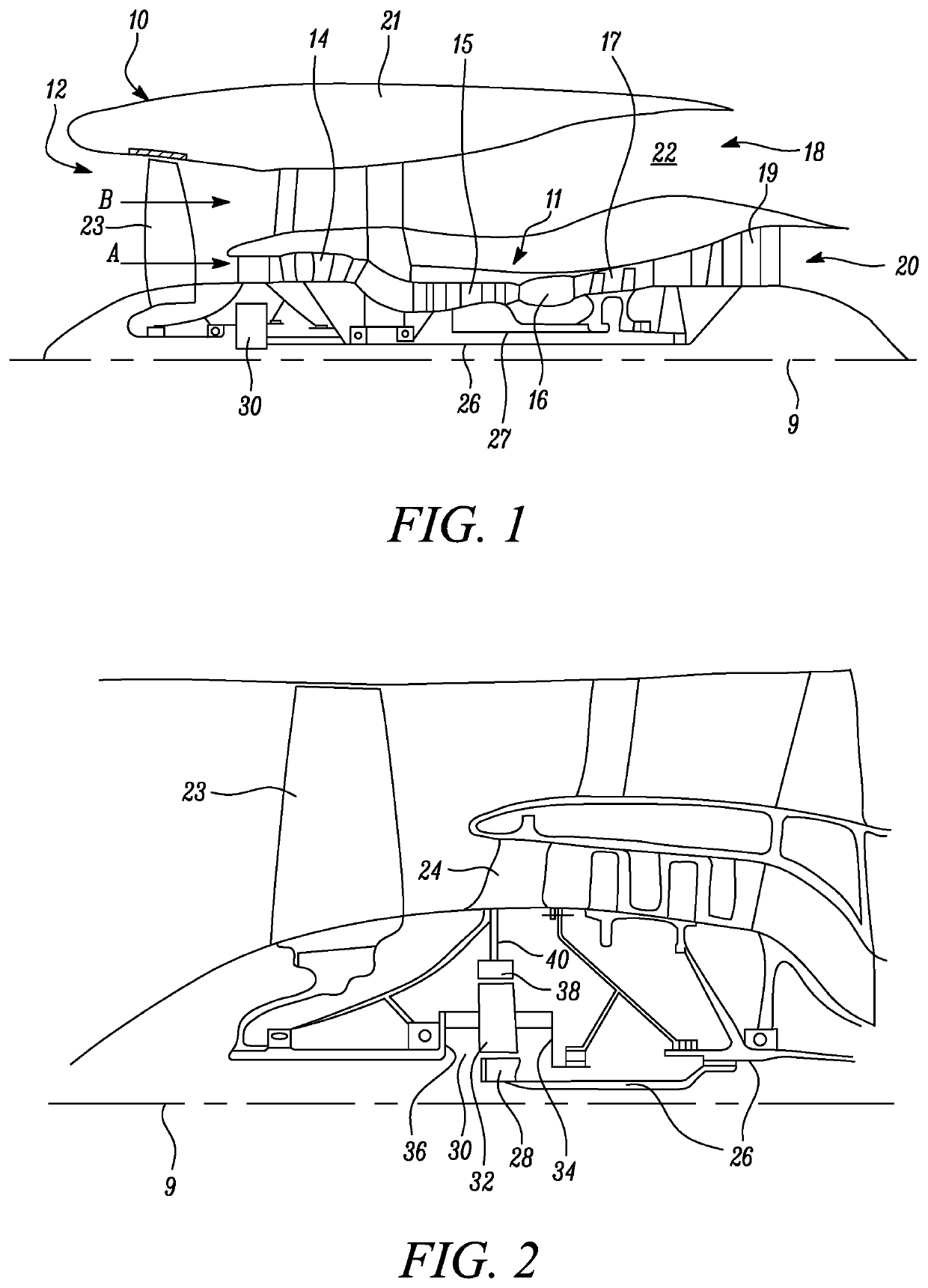
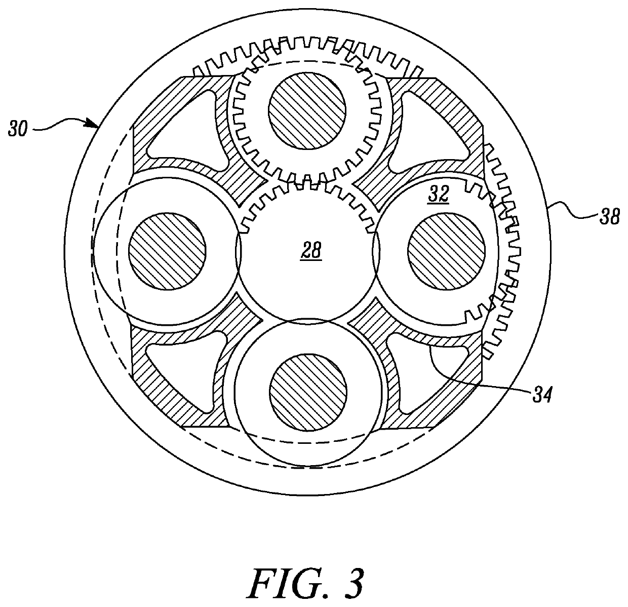
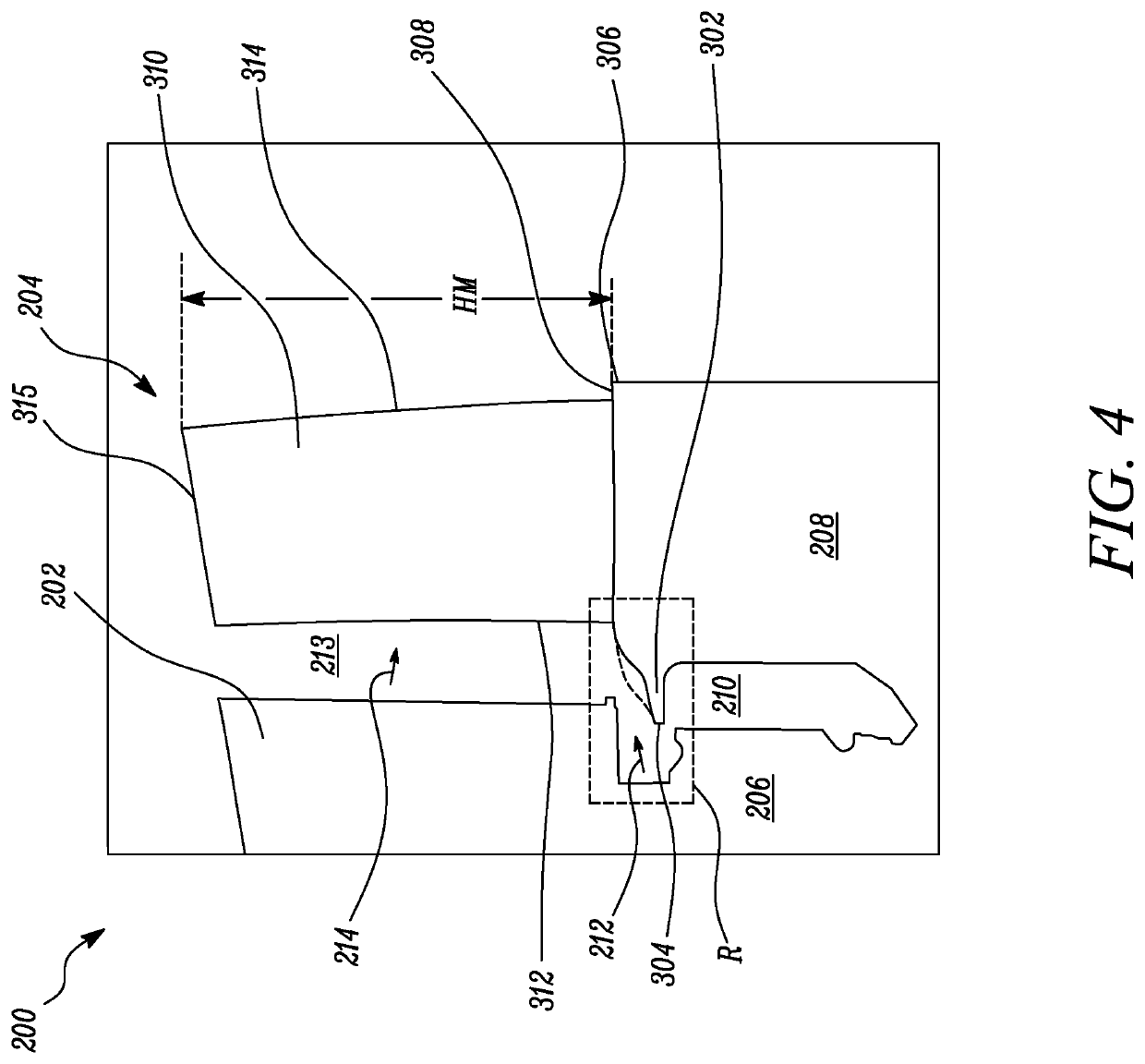
[0080]FIG. 1 illustrates a gas turbine engine 10 having a principal rotational axis 9. The engine 10 comprises an air intake 12 and a propulsive fan 23 that generates two airflows: a core airflow A and a bypass airflow B. The gas turbine engine 10 comprises a core 11 that receives the core airflow A. The engine core 11 comprises, in axial flow series, a low pressure compressor 14, a high-pressure compressor 15, combustion equipment 16, a high-pressure turbine 17, a low pressure turbine 19 and a core exhaust nozzle 20. A nacelle 21 surrounds the gas turbine engine 10 and defines a bypass duct 22 and a bypass exhaust nozzle 18. The bypass airflow B flows through the bypass duct 22. The fan 23 is attached to and driven by the low pressure turbine 19 via a shaft 26 and an epicyclic gearbox 3...


PUM


Abstract

An aerofoil assembly includes a platform and a plurality of aerofoils extending radially outward from the platform. The platform has a first edge, a second edge, and a platform surface disposed between the first edge and the second edge. Each aerofoil has a leading edge proximal to the first edge and a trailing edge distal to the first edge. A pitch spacing is defined between the leading edges of adjacent aerofoils along the platform surface. A mid-pitch location is defined midway along the pitch spacing. The platform defines one or more recesses disposed between the leading edges of the plurality of aerofoils and the first edge. Each of the one or more recesses is disposed proximal to the mid-pitch location between adjacent aerofoils.

Description

CROSS-REFERENCE TO RELATED APPLICATIONS[0001]This specification is based upon and claims the benefit of priority from IN Patent Application Number 202011006225 filed on 13 Feb. 2020, and UK Patent Application Number 2004925.0 filed on 3 Apr. 2020, the entire contents of which are incorporated herein by reference.BACKGROUNDField of the Disclosure[0002]The present disclosure is related to an aerofoil assembly and a method of reducing losses in the aerofoil assembly.Description of the Related Art[0003]Gas turbine engines typically employ rows of blades on wheels / disks of a rotor assembly, which alternate with rows of stationary vanes on a stator or nozzle assembly. Axial and / or radial openings at an interface between rotating blades and stationary vanes can allow hot combustion gases to exit a hot gas path and enter an intervening wheel space between the rows.[0004]To limit such incursion of hot gases, cooling air or purge air is often introduced into a wheel space between the rows. Th...

Claims


Application Information

Patent Timeline
Patent Type & Authority Applications(United States)
IPC IPC(8): F01D5/02
CPCF01D5/022F05D2230/60F05D2220/32F01D5/141F01D5/143F01D5/145F05D2240/80F05D2270/17F01D5/14
Inventor CHOUHAN, ROHITBHAUMIK, SOUMYIK
Owner ROLLS ROYCE PLC
Why Eureka
Try Eureka