Eureka AIR delivers breakthrough ideas for toughest innovation challenges, trusted by R&D personnel around the world.

Sheet feed device

a technology of sheet feeding and feeder, which is applied in the direction of transportation and packaging, thin material processing, article separation, etc., can solve the problems of generating floating uneven sheets, and reducing the accuracy of the following control, so as to reduce the problem of sheet feeding or suppress the effect of problem

Active Publication Date: 2021-09-16
RISO KAGAKU CORP
View PDF5 Cites 0 Cited by
  • Summary
  • Abstract
  • Description
  • Claims
  • Application Information

AI Technical Summary

Benefits of technology

The patent text describes a sheet feed device that can reduce problems with sheet feeding, such as multiple feeding of sheets and no sheet feeding. The device aims to decrease or suppress the influence of noise and floating unevenness of sheets on the control of the sheet feed tray's height position. In summary, the technical effect of this patent is to improve the accuracy and reliability of sheet feeding.

Problems solved by technology

Moreover, the accuracy of the following control may also be decreased due to the unsuitability of a threshold value prepared beforehand, the unsuitability being caused by the individual differences of sheet feed devices.
Decrease in the accuracy of the following control may cause problems in sheet feeding such as multiple feeding occurred due to too many floated sheets, no sheet feeding occurred due to too few floated sheets, and the like.
Moreover, in the sheet feed device above, floating unevenness of sheets may be generated when the sheets are floated due to worsening of the sheet alignment on the sheet feed tray caused by air blow and the like.
And noise may be generated in the sensor value due to the floating unevenness of sheets in the above described control of the height position of the sheet feed tray in accordance with decrease in the number of sheets.
Due to the influence of the noise, the accuracy of the control of the height position of the sheet feed tray may be decreased, which causes problems in sheet feeding such as multiple feeding of sheets, no sheet feeding, and the like.

Method used


Image

  • Sheet feed device
  • Sheet feed device
  • Sheet feed device

Examples


first embodiment

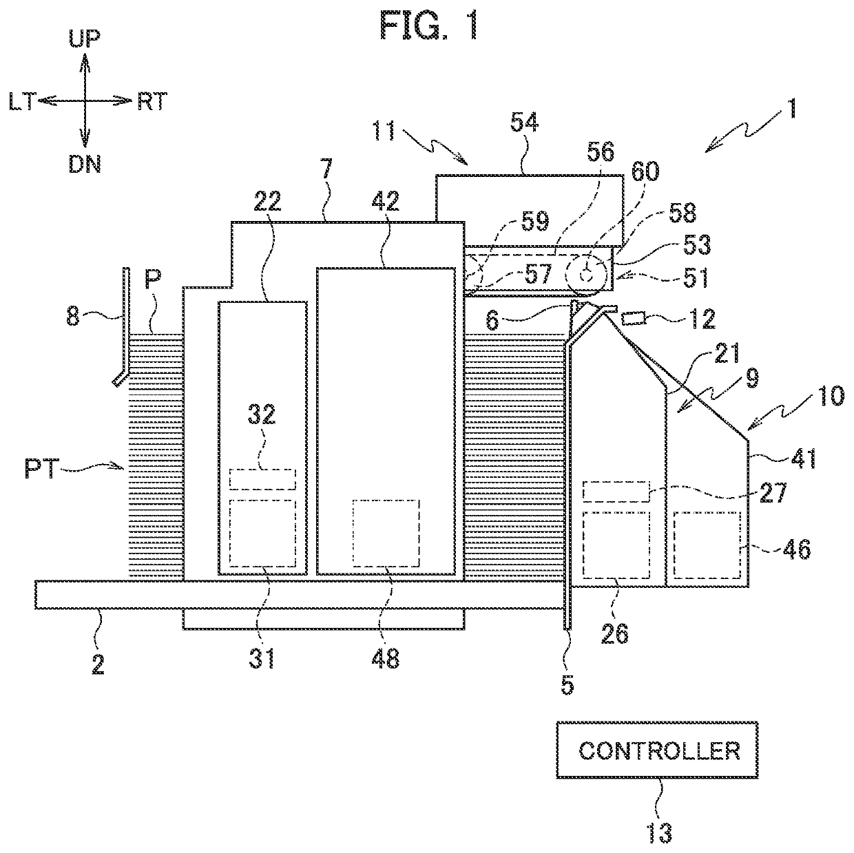
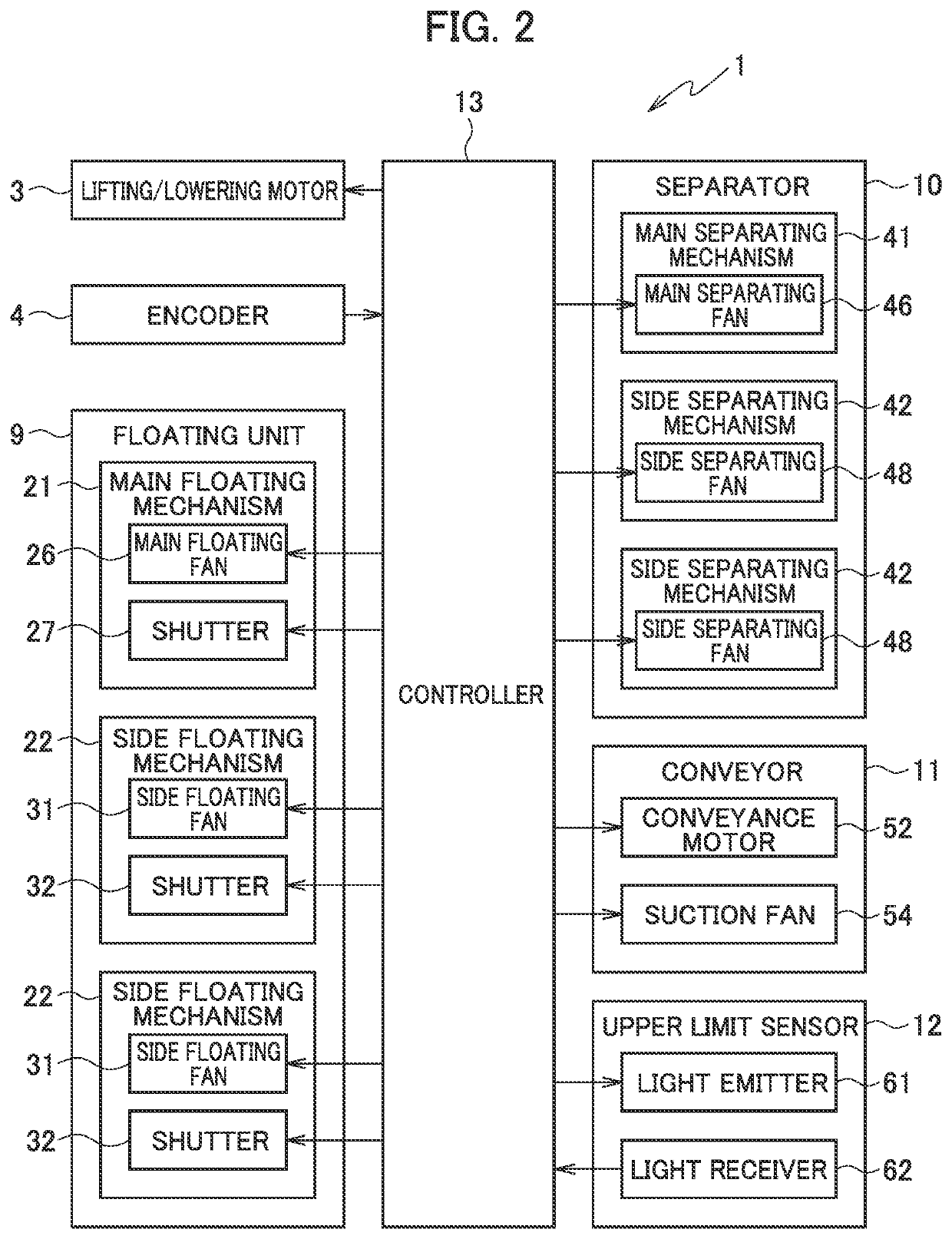
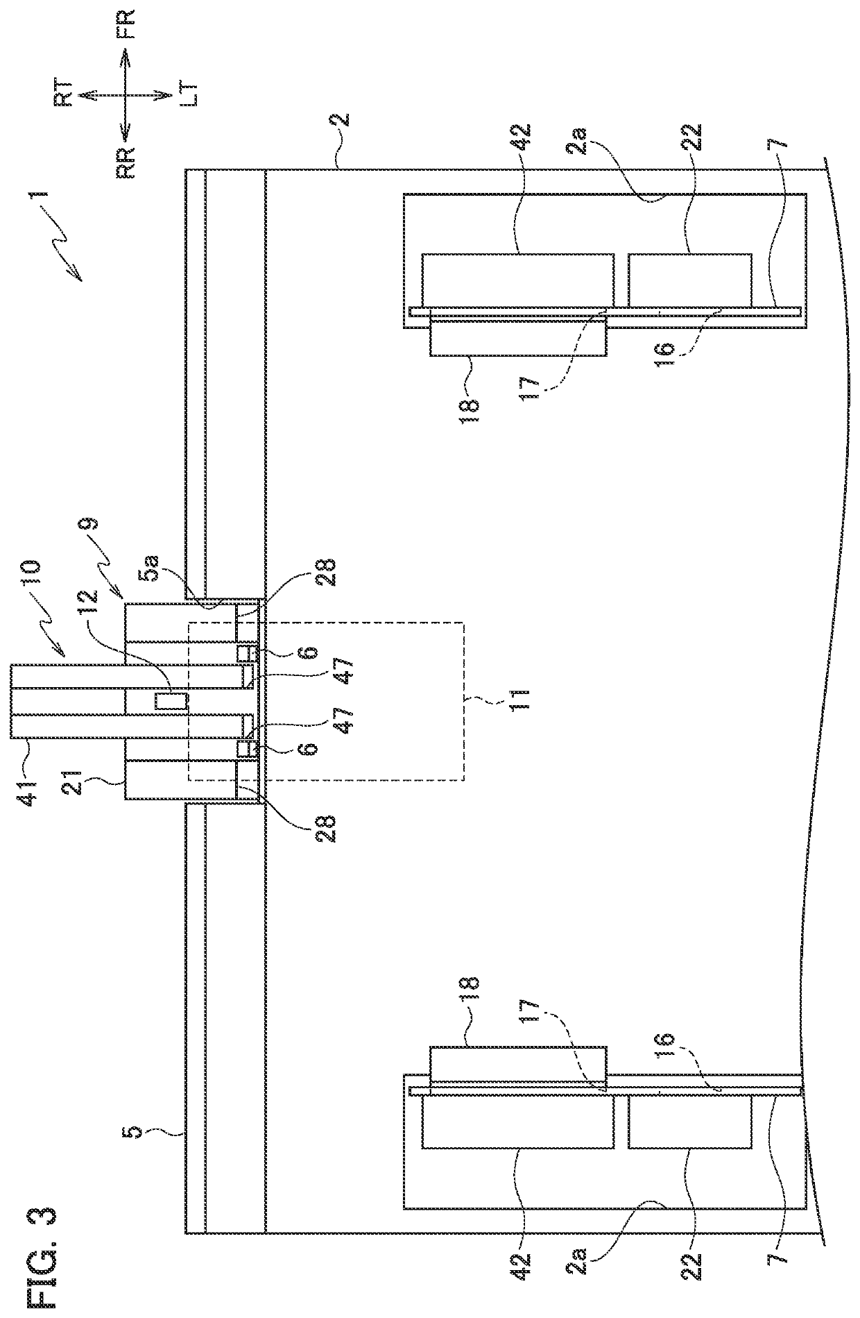
[0078]Next, a first embodiment is described. The controller 13 controls to drive the floating unit 9 and the separator 10 to float sheets P in the upper portion of the sheet stack PT on the sheet feed tray 2 and suck the top sheet P to the conveyance surfaces 56b and drive the conveyor 11 to convey and feed the top sheet P to the sheet feed destination. In the operation above, the controller 13 performs an on and off control of the floating unit 9 for blowing air to sheets P for each sheet conveyed by the conveyor 11, in order to separate the top sheet P from the second and subsequent sheets P from the top.

[0079]The controller 13, during the sheet feed operation, acquires an amount of received light (a sensor value) at the light receiver 62 during floating of sheets P by the floating unit 9 each time each sheet P is conveyed by the conveyor 11 and performs a following control of lifting the sheet feed tray 2 when the acquired amount of received light is less than a following thresho...

second embodiment

[0135]Next, a second embodiment is described. The controller 13 controls to drive the floating unit 9 and the separator 10 to float sheets P on the sheet feed tray 2 and suck the top sheet P to the conveyance surfaces 56b and drive the conveyor 11 to convey and feed the top sheet P to the sheet feed destination. In the operation above, the controller 13 performs an on and off control of the floating unit 9 for blowing air to sheets P for each sheet conveyed by the conveyor 11, in order to separate the top sheet P from the second and subsequent sheets P from the top. That is, as described below, the controller 13 controls to drive the floating unit 9 to stop blowing air in a float airflow stop period (stop period) set in each conveyance cycle of sheets P conveyed by the conveyor 11.

[0136]Moreover, the controller 13 performs a following control of lifting the sheet feed tray 2 in response to decrease of the remaining sheets P on the sheet feed tray 2 due to sheet feeding. As described...

third embodiment

[0191]In the third embodiment, the controller 13 performs a following control using moving average values as the upper surface position information. Each of the moving average values is an average value of the sensor values of the upper limit sensor 12 acquired in the latest float airflow stop periods of a prescribed moving average number of times described below.

[0192]The following control according to the third embodiment is described with reference to the flowchart of FIG. 12. The processing of the flowchart of FIG. 12 is started by the start of the sheet feed operation. Note that the sheet feed operation of the third embodiment is the same as that of the second embodiment.

[0193]The processings of steps S111 to S115 of FIG. 12 are the same as the processings of steps S101 to S105 of FIG. 11 described above.

[0194]In step S116, the controller 13 determines whether a number of acquisition times of the sensor values from the start of the sheet feed operation of this time is less than...


PUM


Abstract

A controller drives a floating unit and a conveyor to perform a sheet feed operation, during the sheet feed operation, acquires an amount of received light at a detector during floating of sheets floated by the floating unit each time each sheet is conveyed by the conveyor, and perform a following control of lifting a stacking tray upon the acquired amount of received light being less than a threshold value. The controller, after start of the sheet feed operation, samples amounts of received light at the detector during floating of the sheets floated by the floating unit, performs a threshold value determination process of determining the threshold value by using the sampled amounts of received light, and starts the following control upon determining the threshold value.

Description

CROSS REFERENCE TO RELATED APPLICATION[0001]This application is based upon and claims the benefit of priority from the prior Japanese Patent Application Nos. 2020-041547 filed on Mar. 11, 2020 and 2020-052953 filed on Mar. 24, 2020, the entire contents of which are incorporated herein by reference.BACKGROUND1. Technical Field[0002]The disclosure relates to a sheet feed device which feeds sheets.2. Related Art[0003]As a sheet feed device which feeds sheets, a sheet feed device which blows air to sheets (a sheet stack) stacked on a sheet feed tray to float sheets, conveys a top (topmost) sheet of the floated sheets while sucking the top sheet with a suction conveyance means, and supplies the top sheet to a sheet feed destination is known.[0004]A sheet feed device described in Japanese Patent Application Publication No. 2019-11150 performs a following control of lifting a sheet feed tray in response to decrease of sheets on the sheet feed tray due to sheet feeding. In the following con...

Claims


Application Information

Patent Timeline
Patent Type & Authority Applications(United States)
IPC IPC(8): B65H1/18B65H3/14B65H1/04B65H5/22
CPCB65H1/18B65H5/224B65H1/04B65H3/14B65H3/08B65H3/48B65H3/128B65H7/14B65H2515/60B65H2511/20B65H2513/512B65H2513/51B65H2801/06B65H2515/20B65H7/16B65H2553/414B65H1/14
Inventor OKAWARA, MIKI
Owner RISO KAGAKU CORP
Why Eureka
Eureka Blog
Learn More