Eureka AIR delivers breakthrough ideas for toughest innovation challenges, trusted by R&D personnel around the world.

Sheet processing apparatus, image forming apparatus including the same, and sheet discharge method

a technology of processing apparatus and discharge method, which is applied in the direction of thin material processing, article delivery, function indicators, etc., can solve the problems of reducing the chances of stopping the subsequent sheet carrying-in, deteriorating alignment, and processing apparatus according to the foregoing patent literature rarely causes a problem

Active Publication Date: 2018-03-22
COPYER
View PDF2 Cites 1 Cited by
  • Summary
  • Abstract
  • Description
  • Claims
  • Application Information

AI Technical Summary

Benefits of technology

The patent text describes an apparatus that can stack sheet bundles without losing their alignment or slowing down their speed, even if the sheet bundle on the placing tray is not fully bound. This allows for faster and more efficient production.

Problems solved by technology

Keeping one or a plurality of subsequent sheets on standby reduces the chances to stop the carry-in of subsequent sheets if the sheet processing on the sheet bundle on the placing tray takes some time.
The sheet processing apparatus according to the foregoing patent literature seldom causes a problem if the sheet bundle placed on the placing tray is bounded by a binding unit such as a stapling unit.
However, it has found that the following problem occurs if the simultaneous bundle discharge described above is performed on unbound sheet bundles, like when unbound sheet bundles are discharged to the stacking tray by changing the placing position on the placing tray sheet bundle by sheet bundle.
This also deteriorates alignment.
However, simply delaying the discharge of the subsequent sheets np1 and np2 increases discharge time.

Method used


Image

  • Sheet processing apparatus, image forming apparatus including the same, and sheet discharge method
  • Sheet processing apparatus, image forming apparatus including the same, and sheet discharge method
  • Sheet processing apparatus, image forming apparatus including the same, and sheet discharge method

Examples


Embodiment Construction

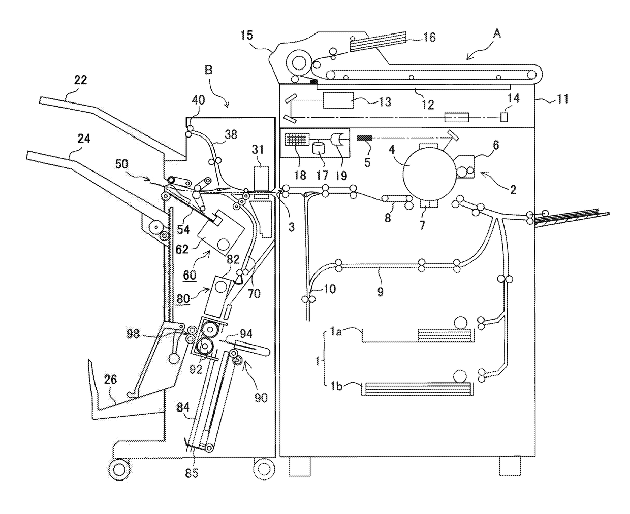
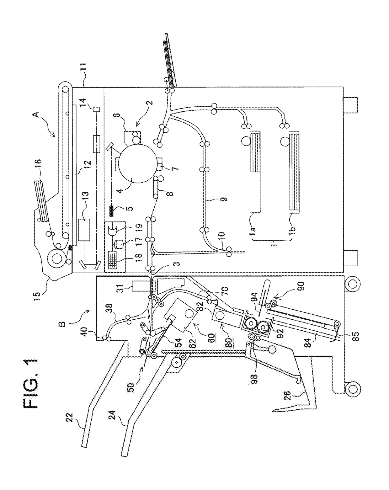
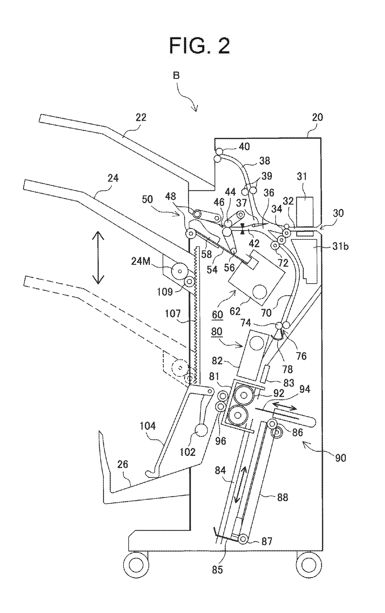
[0046]A mode for carrying out the invention will be described below with reference to the drawings. FIG. 1 is an overall configuration diagram showing an image forming system including an image forming apparatus A and a sheet processing apparatus B according to the present invention. FIG. 2 is an explanatory diagram showing a detailed configuration of the sheet processing apparatus B.

[0047]In the accompanying drawings, similar components are designated by the same reference numerals throughout the entire specification.

[Image Forming System]

[0048]The image forming system shown in FIG. 1 includes the image forming apparatus A and the sheet processing apparatus B. A carry-in port 30 of the sheet processing apparatus B is connected to a main body discharge port 3 of the image forming apparatus A. The image forming system is configured so that sheets on which images are formed by the image forming apparatus A are stapled by the sheet processing apparatus B and stored on a first stacking ...


PUM

PropertyMeasurementUnit
Timeaaaaaaaaaa
Widthaaaaaaaaaa

Abstract

A sheet processing apparatus includes a sheet processing unit that processes a sheet placed on a placing tray, a discharge roller that discharges the sheet processed on the placing tray to a stacking tray, a conveyance roller that discharges a sheet to the placing tray or conveys a subsequent sheet from upstream to downstream of the discharge roller and switchback-conveys the subsequent sheet upstream again, and a standby path (branch path) that keeps the sheet switched back by the conveyance roller on standby. The subsequent sheet is conveyed to a downstream side of the discharge roller by the conveyance roller and then returned to an upstream side again by switchback conveyance. During the switchback conveyance, the discharge roller nips and discharges the sheets on the placing tray to the stacking tray.

Description

BACKGROUND OF THE INVENTION1. Field of the Invention[0001]The present invention relates to a sheet processing apparatus for applying processing to sheets and an image forming apparatus, and more particularly to improvement of sheet alignment when discharging a sheet bundle from a placing tray which processes sheets.2. Description of the Related Art[0002]Some image forming apparatuses, like a copying machine, a laser beam printer, a facsimile, and combined machines thereof, may conventionally include a sheet processing apparatus for performing sheet processing such as binding processing and sort processing on image-formed sheets.[0003]Such an image forming apparatus performs so-called buffer processing in which a subsequent sheet or sheets are once kept on standby to reduce delay of carry-in of subsequent sheets while the binding or sort processing is performed on a preceding sheet bundle on a placing tray. Keeping one or a plurality of subsequent sheets on standby reduces the chance...

Claims


Application Information

Patent Timeline
IPC IPC(8): B65H33/08B65H31/24B65H37/04B65H37/06
CPCB65H33/08B65H31/24B65H37/04B65H37/06B65H2301/42192B65H2801/06B65H29/66B65H31/08B65H39/00B65H83/00B65H29/145B65H31/02B65H31/3027B65H31/36B65H31/38B65H43/00B65H2301/1635B65H2301/4212B65H2301/4213B65H2301/42194B65H2403/942B65H2408/1222B65H2511/224B65H2511/30B65H2801/27B65H2220/01B65H2220/02
Inventor NAKANO, TAKAHIRO
Owner COPYER
Why Eureka
Eureka Blog
Learn More