Transcoder target bitrate prediction techniques

Pending Publication Date: 2021-09-30
ALIBABA GRP HLDG LTD
3 Cites 1 Cited by

AI-Extracted Technical Summary

Problems solved by technology

Encoding above a factor of ten is typically lossy, wherein the visual quality of the content is impacted.
Transcoding can also be a lossy processing and cumulative with the encoding losses.
Typically, the original input content is not available for a brute force search of the transcoding parameters.
A brute force det...

Method used

[0033]Aspects of the present technology can advantageously estimate a minimum target bit rate for use as the transcoder bitrate that satisfies a predetermined quality. The estimated transcoder bitrate can advantageously increase t...

Benefits of technology

[0004]In one embodiment, a computing system can include one or more processors, memory and one or more transcoders. Instructions stored in the memory can cause the processor to perform a video encoding method including receiving a first encoded content, and estimating a transcoder bitrate based on regression of a video quality estimator over the first encoded content and the second encoded content. The video encoder can be configured to convert the first encoded content to the second encoded content based on one or more transcoding parameter values including the estimated transcoder bitrate.
[0005]In another embodiment, a transcoder method can include receiving a first encoder content and a set of encoder information of the first encoded content. It can be determined if the received set of encoder information matches one of a plurality of existing sets of encoder information. When the received encoder information does not match one of the plurality of existing sets of encoder information, a predetermined target bitrate can be selected as a trans...

Abstract

Transcoding bitrate prediction techniques can include receiving a first encoded content. A transcoder bitrate can be estimated based on regression over a video quality estimator of the first encoded content and a second encoded content. The estimated transcoder bitrate can be utilized to transcoding the first encoded content into the second encoded.

Application Domain

Digital video signal modification

Technology Topic

Video qualityReal-time computing +5

Image

  • Transcoder target bitrate prediction techniques
  • Transcoder target bitrate prediction techniques
  • Transcoder target bitrate prediction techniques

Examples

  • Experimental program(1)

Example

[0014]Reference will now be made in detail to the embodiments of the present technology, examples of which are illustrated in the accompanying drawings. While the present technology will be described in conjunction with these embodiments, it will be understood that they are not intended to limit the technology to these embodiments. On the contrary, the invention is intended to cover alternatives, modifications and equivalents, which may be included within the scope of the invention as defined by the appended claims. Furthermore, in the following detailed description of the present technology, numerous specific details are set forth in order to provide a thorough understanding of the present technology. However, it is understood that the present technology may be practiced without these specific details. In other instances, well-known methods, procedures, components, and circuits have not been described in detail as not to unnecessarily obscure aspects of the present technology.
[0015]Some embodiments of the present technology which follow are presented in terms of routines, modules, logic blocks, and other symbolic representations of operations on data within one or more electronic devices. The descriptions and representations are the means used by those skilled in the art to most effectively convey the substance of their work to others skilled in the art. A routine, module, logic block and/or the like, is herein, and generally, conceived to be a self-consistent sequence of processes or instructions leading to a desired result. The processes are those including physical manipulations of physical quantities. Usually, though not necessarily, these physical manipulations take the form of electric or magnetic signals capable of being stored, transferred, compared and otherwise manipulated in an electronic device. For reasons of convenience, and with reference to common usage, these signals are referred to as data, bits, values, elements, symbols, characters, terms, numbers, strings, and/or the like with reference to embodiments of the present technology.
[0016]It should be borne in mind, however, that these terms are to be interpreted as referencing physical manipulations and quantities and are merely convenient labels and are to be interpreted further in view of terms commonly used in the art. Unless specifically stated otherwise as apparent from the following discussion, it is understood that through discussions of the present technology, discussions utilizing the terms such as “receiving,” and/or the like, refer to the actions and processes of an electronic device such as an electronic computing device that manipulates and transforms data. The data is represented as physical (e.g., electronic) quantities within the electronic device's logic circuits, registers, memories and/or the like, and is transformed into other data similarly represented as physical quantities within the electronic device.
[0017]In this application, the use of the disjunctive is intended to include the conjunctive. The use of definite or indefinite articles is not intended to indicate cardinality. In particular, a reference to “the” object or “a” object is intended to denote also one of a possible plurality of such objects. The use of the terms “comprises,”“comprising,”“includes,”“including” and the like specify the presence of stated elements, but do not preclude the presence or addition of one or more other elements and or groups thereof. It is also to be understood that although the terms first, second, etc. may be used herein to describe various elements, such elements should not be limited by these terms. These terms are used herein to distinguish one element from another. For example, a first element could be termed a second element, and similarly a second element could be termed a first element, without departing from the scope of embodiments. It is also to be understood that when an element is referred to as being “coupled” to another element, it may be directly or indirectly connected to the other element, or an intervening element may be present. In contrast, when an element is referred to as being “directly connected” to another element, there are not intervening elements present. It is also to be understood that the term “and or” includes any and all combinations of one or more of the associated elements. It is also to be understood that the phraseology and terminology used herein is for the purpose of description and should not be regarded as limiting.
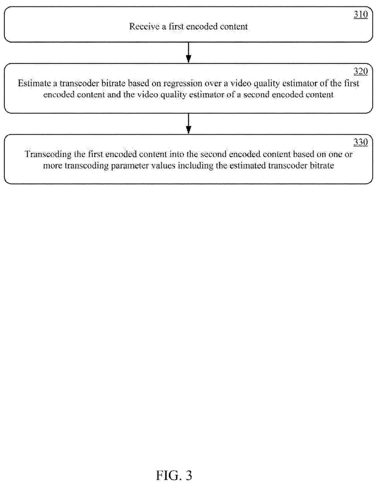
[0018]Referring now to FIG. 3, a transcoder method, in accordance with aspects of the present technology, is shown. The method can include receiving a first encoder content, at 310. In one implementation, the first encoder content can be video content encoded in a first encoder format.
[0019]At 320, a transcoder bitrate can be estimated based on regression over a video quality estimator of the first encoded content and a second encoded content. The second encoded content can be a transcoding of the first video content. The regression can be a linear or polynomial regression over the video quality estimator of the first encoded content and the second encoded content. In one implementation, the transcoded bitrate can be estimated based on a linear regression over a video multimethod assessment fusion (VMAF) estimator. For example, a predetermined VMAF (Pred_VMAF) can be a function of a bitrate of an input encoded content (e.g., first encoded content) and a bitrate of an output encoded content (e.g., second encoded content) for the transcoder as expressed by Equation 1:
Pred ⁢ _ ⁢ VMAF = ⁢ f ⁡ ( bitrate_in ⁢ _video , bitrate_out ⁢ _video ) = ⁢ a * ln ⁡ ( bitrate_in ⁢ _video ) + b * ln ⁡ ( bitrate_out ⁢ _video ) ( 1 )
wherein bitrate_in_video is the bitrate of the input encoded content and bitrate_out_video is the bitrate of the output encoded content. The target VMAF (Target_VMAF) can be a function of a bitrate of an input encoded content (e.g., first encoded content) and a bitrate of an output encoded content (e.g., second encoded content) for the transcoder as expressed by Equation 2:
Target_VMAF = ⁢ f ⁡ ( bitrate_in ⁢ _video , bitrate_out ⁢ _video ) = ⁢ a * ln ⁡ ( bitrate_in ⁢ _video ) + ⁢ b * ln ⁢ ( bitrate_out ⁢ _video ) + c ( 2 )
The target bitrate (Bitrate_out_video) can be expressed in accordance with Equation 3:
Bitrate_out_video=e(Target VMAF −(α*ln(bitrate_in_video)+c)/α (3)
[0020]In another example, the transcoded bitrate can be estimated based on a polynomial regression over the VMAF estimator. For example, a predetermined VMAF (Pred_VMAF) can be a function of a bitrate of an input encoded content (e.g., first encoded content) and a bitrate of an output encoded content (e.g., second encoded content) for the transcoder as expressed by Equation 4:
Pred ⁢ _ ⁢ VMAF = ⁢ f ⁡ ( bitrate_in ⁢ _video , bitrate_out ⁢ _video ) = ⁢ a * x + b * x 2 + c * y + d * y 2 + f ( 4 )
wherein bitrate_in_video is the bitrate of the input encoded content, bitrate_out_video is the bitrate of the output encoded content, x=ln(bitrate_in_video), and y=ln(bitrate_out_video). The target VMAF (Target_VMAF) can be a function of a bitrate of an input encoded content (e.g., first encoded content) and a bitrate of an output encoded content (e.g., second encoded content) for the transcoder as expressed by Equation 5:
Target_VMAF = ⁢ f ⁡ ( bitrate_in ⁢ _video , bitrate_out ⁢ _video ) = ⁢ a * x + b * x 2 + c * y + d * y 2 + e ( 5 )
The target bitrate (Bitrate_out_video) can be expressed in accordance with Equation 6:
Bitrate_out ⁢ _video = e ( d 2 - 4 ⁢ ⁢ f * c - d ) / 2 ⁢ ⁢ c ( 6 )
where f=e+a*x2+b*x−Target_VMAF
[0021]At 330, the first encoded content can be transcoded into the second encoded content based on one or more transcoding parameter values including the estimated transcoder bitrate.
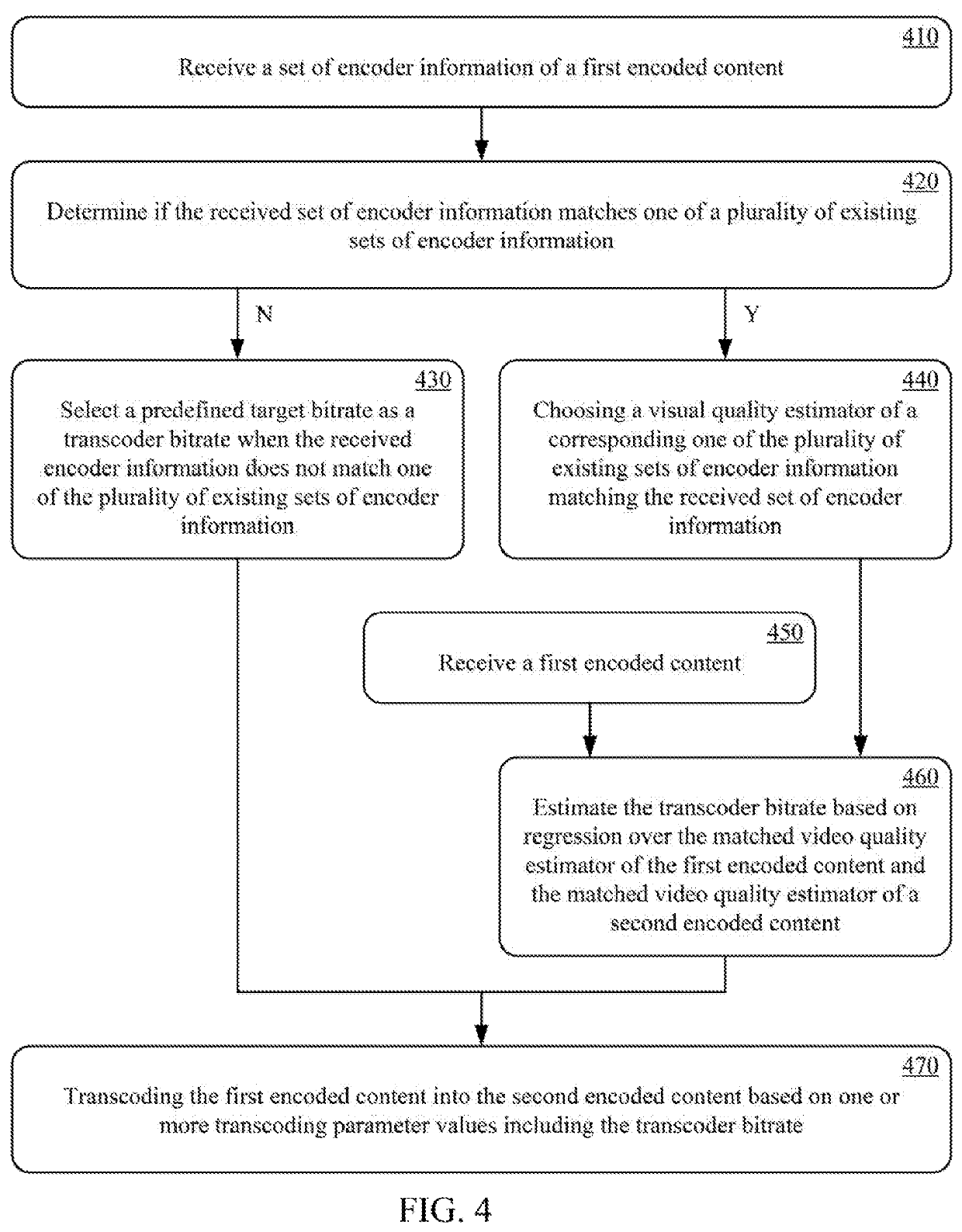
[0022]Referring now to FIG. 4, another transcoder method, in accordance with aspects of the present technology, is shown. The method can include receiving a set of encoder information of a first encoded content, at 410. In one implementation, the encoder information can include the encoder type, encoding parameters and the like of an encoder.
[0023]At 420, it can be determined if the received set of encoder information matches one of a plurality of existing sets of encoder information. In one implementation, the plurality of existing sets of encoder information and corresponding visual quality estimator can be determined by training a plurality of different visual quality estimators on different sets of encoding information. For example, a plurality of VMAF estimators can be trained based on a plurality of different encoding information. At 430, a predefined target bitrate can be selected as a transcoder bitrate when the received encoder information does not match one of the plurality of existing sets of encoder information. In one implementation, the predefined target bitrate can be a redundant high default target bitrate.
[0024]At 440, a visual quality estimator of the corresponding one of the plurality of existing sets of encoder information can be selected when the received encoder information matches the corresponding one of the plurality of existing sets of encoder information. For example, the VMAF estimator of a corresponding one of the plurality of VMAF estimators that matches the encoding information of the encoder.
[0025]At 450, a first encoded content of an encoder for the received encoder information can be received. At 460, the transcoder bitrate can be estimated based on regression over the matched video quality estimator of the first encoded content and a second encoded content. The second encoded content can be a transcoding of the first video content. The regression can be a linear or polynomial regression over the video quality estimator of the first encoded content and the second encoded content. In one implementation, the transcoded bitrate can be estimated based on a linear regression over the VMAF estimator. For example, a predetermined VMAF (Pred_VMAF) can be a function of a bitrate of an input encoded content (e.g., first encoded content) and a bitrate of an output encoded content (e.g., second encoded content) for the transcoder as expressed by Equation 1:
Pred ⁢ _ ⁢ VMAF = ⁢ f ⁡ ( bitrate_in ⁢ _video , bitrate_out ⁢ _video ) = ⁢ a * ln ⁡ ( bitrate_in ⁢ _video ) + ⁢ b * ln ⁡ ( bitrate_out ⁢ _video ) ( 1 )
wherein bitrate_in_video is the bitrate of the input encoded content and bitrate_out_video is the bitrate of the output encoded content. The target VMAF (Target_VMAF) can be a function of a bitrate of an input encoded content (e.g., first encoded content) and a bitrate of an output encoded content (e.g., second encoded content) for the transcoder as expressed by Equation 2:
Target_VMAF = ⁢ f ⁡ ( bitrate_in ⁢ _video , bitrate_out ⁢ _video ) = ⁢ a * ln ⁡ ( bitrate_in ⁢ _video ) + ⁢ b * ln ⁡ ( bitrate_out ⁢ _video ) + c ( 2 )
The constants a, b and c can be obtained from the training of the plurality of different visual quality estimators on the different sets of encoding information. The target bitrate (Bitrate_out_video) can be expressed in accordance with Equation 3:
Bitrate_out_video=e(Target VMAF −(α*ln(bitrate_in_video)+c)/α (3)
[0026]In another example, the transcoded bitrate can be estimated based on a polynomial regression over the VMAF estimator. For example, a predetermined VMAF (Pred_VMAF) can be a function of a bitrate of an input encoded content (e.g., first encoded content) and a bitrate of an output encoded content (e.g., second encoded content) for the transcoder as expressed by Equation 4:
Pred ⁢ _ ⁢ VMAF = ⁢ f ⁡ ( bitrate_in ⁢ _video , bitrate_out ⁢ _video ) = ⁢ a * x + b * x 2 + c * y + d * y 2 + f ( 4 )
wherein bitrate_in_video is the bitrate of the input encoded content, bitrate_out_video is the bitrate of the output encoded content, x=ln(bitrate_in_video), and y=ln(bitrate_out_video). The target VMAF (Target_VMAF) can be a function of a bitrate of an input encoded content (e.g., first encoded content) and a bitrate of an output encoded content (e.g., second encoded content) for the transcoder as expressed by Equation 5:
Target_VMAF = ⁢ f ⁡ ( bitrate_in ⁢ _video , bitrate_out ⁢ _video ) = ⁢ a * x + b * x 2 + c * y + d * y 2 + e ( 5 )
The constants a, b, c, d and e can be obtained from the training of the plurality of different visual quality estimators on the different sets of encoding information. The target bitrate (Bitrate_out_video) can be expressed in accordance with Equation 6:
Bitrate_out ⁢ _video = e ( d 2 - 4 ⁢ ⁢ f * c - d ) / 2 ⁢ ⁢ c ( 6 )
where f=e+a*x2+b*x−Target_VMAF
[0027]At 470, the first encoded content can be transcoded into the second encoded content based on one or more transcoding parameter values including the transcoder bitrate. For example, when the received encoder information does not match one of the plurality of existing sets of encoder information, the first encoded content can be transcoded into the second encoded content at the predetermined bitrate. When the received encoder information matches a corresponding one of the plurality of existing sets of encoder information, the first encoded content can be transcoded into the second encoded content at the estimated transcoder bitrate based on regression over the matched video quality estimator of the first encoded content and the second encoded content.
[0028]Referring now to FIG. 5, a computing system for transcoding content, in accordance with aspects of the present technology, is shown. The computing system 500 can include one or more processors 502, memory 504 and one or more transcoders 506. The one or more transcoders 506 can be implemented in separate hardware, or in software executing on the one or more processes 502. In one implementation, the computing system 500 can be a server computer, a data center, a cloud computing system, a stream service system, an internet service provider system, a cellular service provider system, or the like.
[0029]The one or more processors 502 can be central processing units (CPU), graphics processing units (GPU), neural processing units (NPU), vector processors, memory processing units, or the like, or combinations thereof. In one implementation, a processor 502 can include one or more communication interfaces, such as peripheral component interface (PCIe4) 508 and inter-integrated circuit (PC) interface 510, an on-chip circuit tester, such as a joint test action group (JTAG) engine 512, a direct memory access engine 514, a command processor (CP) 516, and one or more cores 518-524. The one or more cores 518-524 can be coupled in a direction ring bus configuration.
[0030]Referring now to FIG. 6, an exemplary processing core, in accordance with aspects of the present technology, is shown. The processing core 600 can include a tensor engine (TE) 610, a pooling engine (PE) 615, a memory copy engine (ME)620, a sequencer (SEQ) 625, an instructions buffer (11)630, a local memory (LM) 635, and a constant buffer (CB) 640. The local memory 635 can be pre-installed with model weights and can store in-use activations on-the-fly. The constant buffer 640 can store constant for batch normalization, quantization and the like. The tensor engine 610 can be utilized to accelerate fused convolution and or matrix multiplication. The pooling engine 615 can support pooling, interpolation, region-of-interest and the like operations. The memory copy engine 620 can be configured for inter- and or intra-core data copy, matrix transposition and the like. The tensor engine 610, pooling engine 615 and memory copy engine 620 can run in parallel. The sequencer 625 can orchestrate the operation of the tensor engine 610, the pooling engine 615, the memory copy engine 620, the local memory 635, and the constant buffer 640 according to instructions from the instruction buffer 630. The processing core 600 can provide video coding efficient computation under the control of operation fused coarse-grained instructions. A detailed description of the exemplary processing unit core 600 is not necessary to an understanding of aspects of the present technology, and therefore will not be described further herein.
[0031]Referring again to FIG. 5, the one or more cores 518-524 can execute one or more sets of computing device executable instructions to perform one or more functions including, but not limited to, a transcoder bitrate predictor 526. The one or more functions can be performed on individual core 518-524, can be distributed across a plurality of cores 518-524, can be performed along with one or more other functions on one or more cores, and or the like.
[0032]The transcoder bitrate predictor 526 can be configured to estimate a transcoder bitrate as described above with reference to FIGS. 3 and 4. The one or more processors 502 can output transcoder parameters 528 including the transcoder bitrate to the one or more transcoders 506. The one or more transcoders 506 can convert the first encoded content to a second content 532 using the transcoder parameters 528 including the transcoder bitrate.
[0033]Aspects of the present technology can advantageously estimate a minimum target bit rate for use as the transcoder bitrate that satisfies a predetermined quality. The estimated transcoder bitrate can advantageously increase the compression efficiency of the transcoder. Aspects of the present technology can also advantageously eliminate the need for a brute force determination of the optimal transcoder bitrate, thereby reducing computational complexity.
[0034]The foregoing descriptions of specific embodiments of the present technology have been presented for purposes of illustration and description. They are not intended to be exhaustive or to limit the present technology to the precise forms disclosed, and obviously many modifications and variations are possible in light of the above teaching. The embodiments were chosen and described in order to best explain the principles of the present technology and its practical application, to thereby enable others skilled in the art to best utilize the present technology and various embodiments with various modifications as are suited to the particular use contemplated. It is intended that the scope of the invention be defined by the claims appended hereto and their equivalents.

PUM

no PUM

Description & Claims & Application Information

We can also present the details of the Description, Claims and Application information to help users get a comprehensive understanding of the technical details of the patent, such as background art, summary of invention, brief description of drawings, description of embodiments, and other original content. On the other hand, users can also determine the specific scope of protection of the technology through the list of claims; as well as understand the changes in the life cycle of the technology with the presentation of the patent timeline. Login to view more.

Similar technology patents

Method and apparatus for testing quality of seal and package integrity

InactiveUS20150316441A1limit scope
Owner:UNIV OF FLORIDA RES FOUNDATION INC

Document contribution management system

ActiveUS20200142545A1limit scope
Owner:MICROSOFT TECH LICENSING LLC

Electronically-controlled water dispensing system

InactiveUS20110260827A1limit scope
Owner:SHAPIRO DAVID ALAN

Export User Data From Defined Region

ActiveUS20140013260A1limit scope
Owner:NAVICO HLDG

Classification and recommendation of technical efficacy words

Why Eureka
Try Eureka