LED driver and LED lighting system for use with a high frequency electronic ballast

a technology of led driver and led lighting system, which is applied in the field of lighting, can solve the problems of insufficient function, inability to operate properly, and inability to protect the protection function of the hf ballast, so as to reduce the switching rate between the two periods, and achieve the effect of reducing the problem of emi

Active Publication Date: 2021-10-21
SIGNIFY HLDG BV
View PDF0 Cites 0 Cited by
  • Summary
  • Abstract
  • Description
  • Claims
  • Application Information

AI Technical Summary

Benefits of technology

[0030]Thus, each cycle of the AC power is divided into a shunt portion and a non-shunt portion. This makes the shunt switching operate at a relatively low frequency, in particular at a same frequency as the AC power, for so that EMI issues are reduced.
[0031]The first period may comprise a plurality of successive AC cycles of the AC power, and the second period may then comprise another plurality of successive AC cycles of the AC power succeeding the first period. The switching rate between the two periods can thus be reduced. The first period for example has substantially the same time length as the second period.

Problems solved by technology

One of the drawbacks of the retrofit LED tube is that it does not function properly in case the LED tube also allows for dimming.
A problem can arise that a protection function of an HF ballast may be undesirably triggered by a connected retrofit lamp, such as an end of life protection based on detection of a DC offset in the delivered HF ballast output.
Thus, there is an issue that some operating modes of the retrofit lamp mean that a DC bias is present in the current drawn from the ballast, and this can result in a protection function being triggered.

Method used


Image

  • LED driver and LED lighting system for use with a high frequency electronic ballast
  • LED driver and LED lighting system for use with a high frequency electronic ballast
  • LED driver and LED lighting system for use with a high frequency electronic ballast

Examples


Embodiment Construction

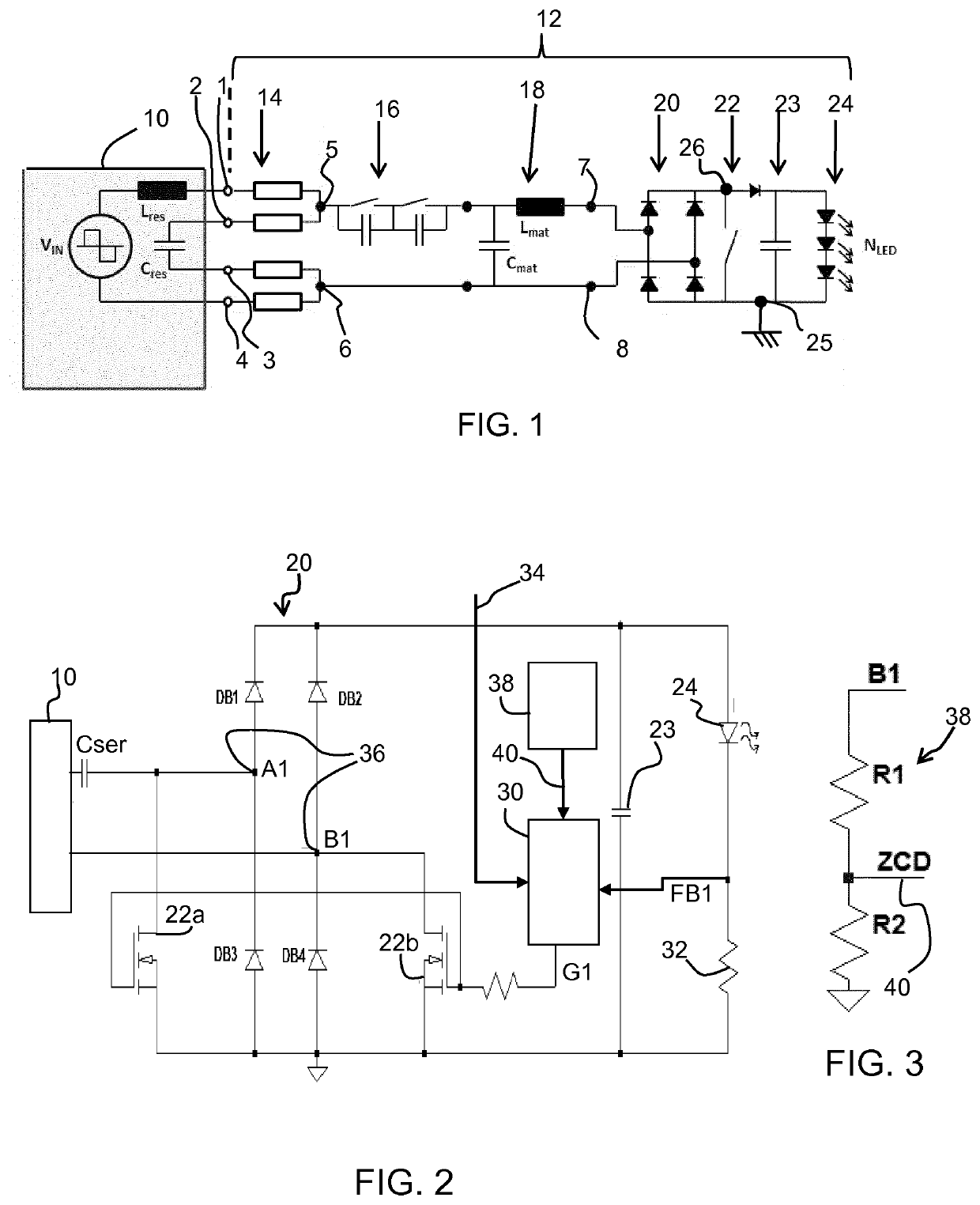
[0075]The invention will be described with reference to the Figures.

[0076]It should be understood that the detailed description and specific examples, while indicating exemplary embodiments of the apparatus, systems and methods, are intended for purposes of illustration only and are not intended to limit the scope of the invention. These and other features, aspects, and advantages of the apparatus, systems and methods of the present invention will become better understood from the following description, appended claims, and accompanying drawings. It should be understood that the Figures are merely schematic and are not drawn to scale. It should also be understood that the same reference numerals are used throughout the Figures to indicate the same or similar parts.

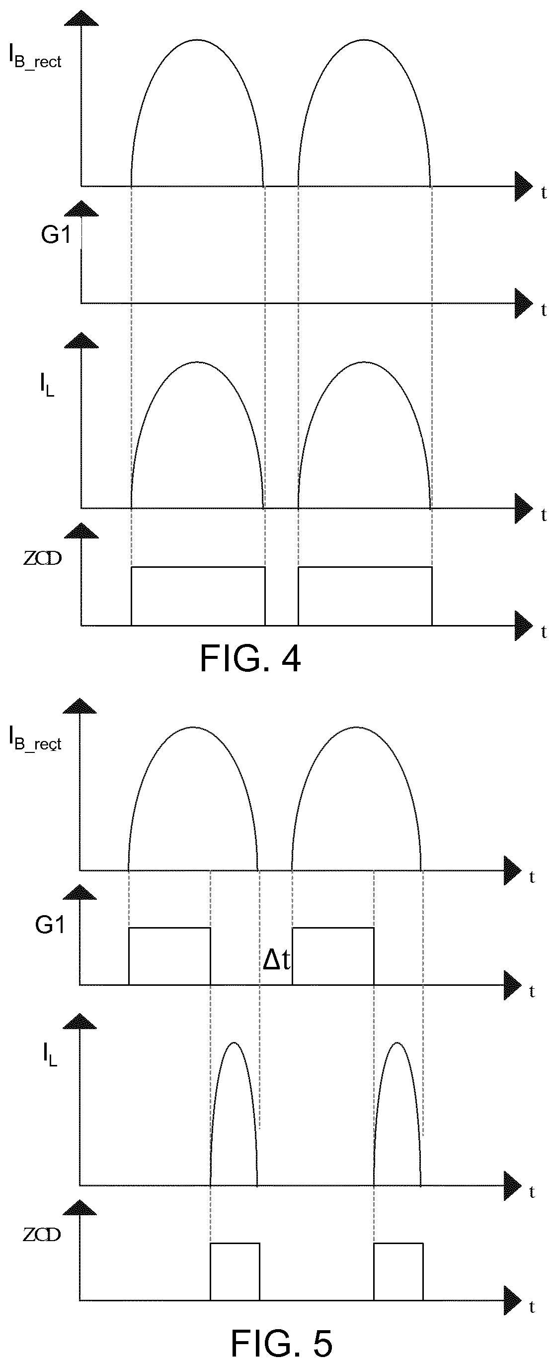
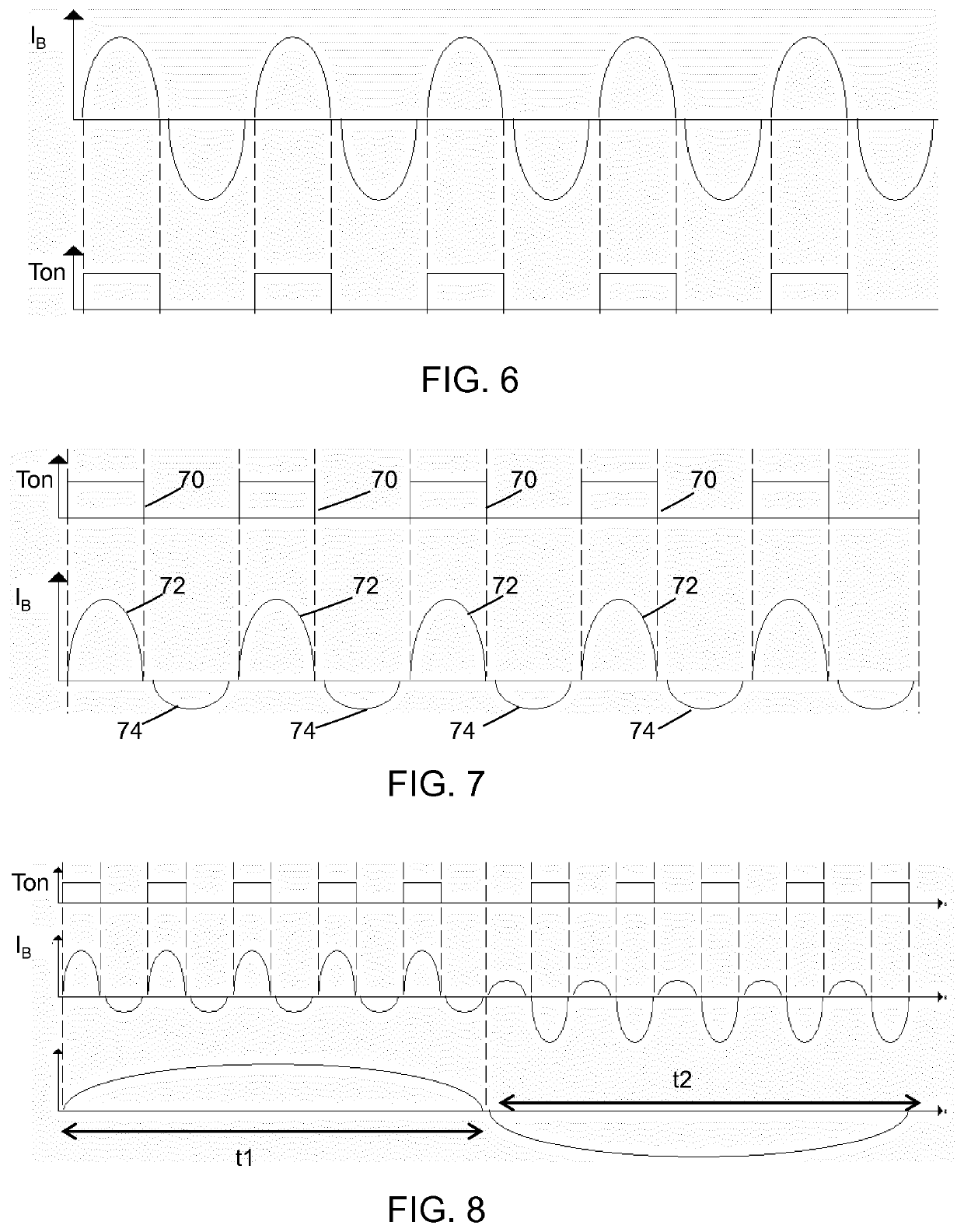
[0077]The invention provides a retrofit LED lamp driver having a shunt switch to alternately shunt (for a first duration) and not shunt (for a second duration) received AC power. The first duration is synchronized with a f...


PUM

PropertyMeasurementUnit
frequencyaaaaaaaaaa
frequencyaaaaaaaaaa
frequencyaaaaaaaaaa

Abstract

The invention provides a retrofit LED lamp driver having a shunt switch to alternately shunt (for a first duration) and not shunt (for a second duration) received AC power. The first duration is concurring with a first polarity of each AC cycle of the AC power, for a first period comprising at least one AC cycle, and the first duration is concurring in a second, opposite polarity of the AC power, for a second period comprising another at least one AC cycle not overlapping with the first duration. Alternating the first and second periods are provided. Any DC offset in the current drawn caused by the shunting operation is thereby cancelled over time.

Description

FIELD OF THE INVENTION[0001]The present invention generally relates to the field of lighting and, more specifically, to a retrofit Light Emitting Diode, LED, lamp. The present invention further relates to a lighting system comprising a high frequency electronic ballast and the retrofit LED lamp, and to a method of operating a retrofit LED lamp.BACKGROUND OF THE INVENTION[0002]Lighting devices have been developed that make use of Light Emitting Diodes, LEDs, for a variety of lighting applications. Owing to their long lifetime and high energy efficiency, LED lamps are nowadays also designed for replacing traditional fluorescent lamps, i.e. for retrofit applications. For such an application, a retrofit LED tube is typically adapted to fit into the socket of the respective lamp fixture to be retrofitted. Moreover, since the maintenance of a lamp is typically conducted by a user, the retrofit LED tube should ideally be readily operational with any type of suitable fixture without the nee...

Claims


Application Information

Patent Timeline
Patent Type & Authority Applications(United States)
IPC IPC(8): H05B45/35H05B45/10H05B45/3725H05B45/3578H05B44/00
CPCH05B45/35H05B45/3578H05B45/3725H05B45/10H05B45/39Y02B20/30
Inventor TAO, HAIMINZHANG, BRIANZHENG, DEREK
Owner SIGNIFY HLDG BV
Why Eureka
Try Eureka