LED splicing display panel

Pending Publication Date: 2021-10-28
SHENZHEN CHINA STAR OPTOELECTRONICS SEMICON DISPLAY TECH CO LTD
View PDF0 Cites 2 Cited by
  • Summary
  • Abstract
  • Description
  • Claims
  • Application Information

AI Technical Summary

Benefits of technology

[0026]Compared to the prior art, the LED splicing display panel provided by the embodiments of the present disclosure effectively eases spatial limitation of part of pixels in key positions by disposing the irregular-shaped sub-pixels and ab

Problems solved by technology

This challenges dimensional compression of an LED chip in a single pixel space, thin film transistors, and designs of related wirings.
Particularly, difficulty of pixel designs is substantially increased in order to achieve seamless splicing, and this greatly affects development of the LED splicing screens toward the direction of small dime

Method used


Image

  • LED splicing display panel
  • LED splicing display panel
  • LED splicing display panel

Examples


first embodiment

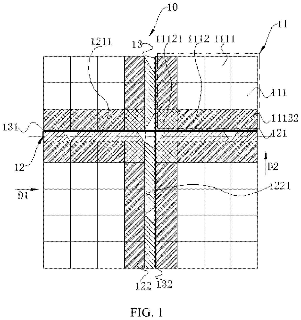
[0031]Illustrated in FIG. 1 is a structural schematic diagram of repeat units of an LED splicing display panel provided by the present disclosure. Furthermore, the LED splicing display panel includes at least one repeat unit 10. Each of the repeat units 10 includes four sub-LED display panels spliced to each other. Display regions 11 of the four sub-LED display panels are arranged in two rows and two columns. Each of the sub-LED display panels includes the display region 11 and fan-out regions 12 respectively corresponding to two adjacent sides of the plurality of display regions 11. Slits 13 are between two adjacent sub-LED display panels. The two adjacent sub-LED display panels share the fan-out regions 12.

[0032]Specifically, sub-pixels 111 are in the four display regions 11. The sub-pixels 111 include irregular-shaped sub-pixels 1112 located on edges of the four display regions 11, and regular-shaped sub-pixels 1111 respectively adjacent to the irregular-shaped sub-pixels 1112. E...

second embodiment

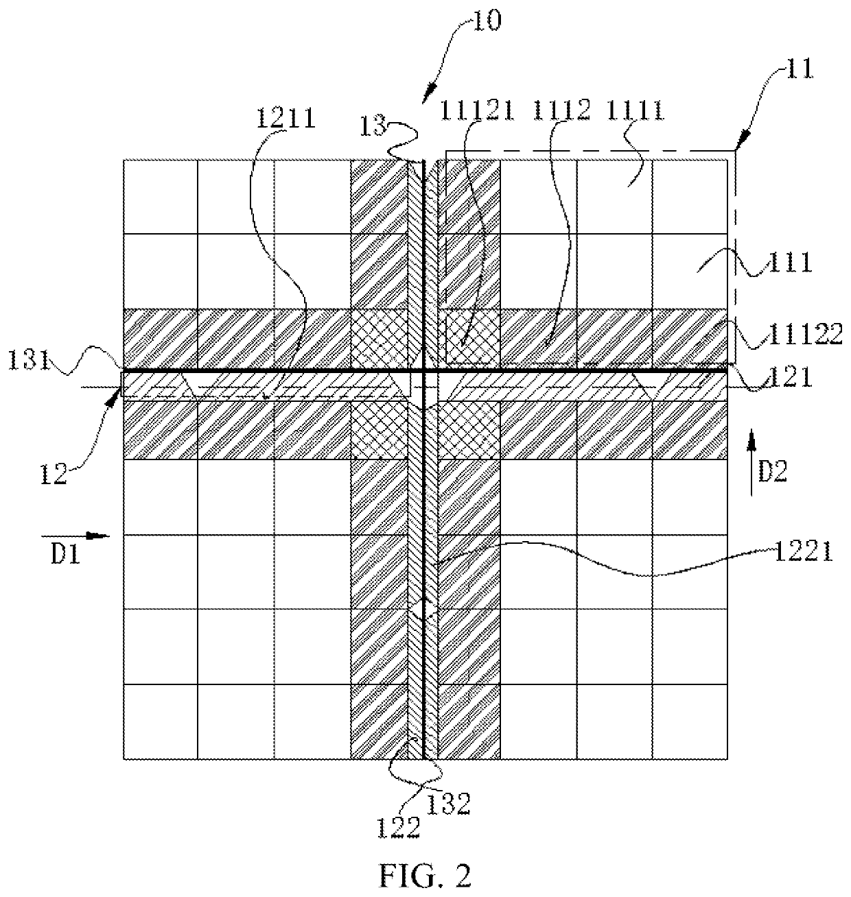
[0041]Illustrated in FIG. 2 is a structural schematic diagram of the repeat units of an LED splicing display panel provided by the present disclosure. Furthermore, the LED splicing display panel includes at least one repeat unit 10. Each of the repeat unit 10 includes four sub-LED display panels spliced to each other. Display regions 11 of the four sub-LED display panels are arranged in two rows and two columns. Each of the sub-LED display panels includes the display region 11 and fan-out regions 12 respectively corresponding to two adjacent sides of the plurality of display regions 11. Slits 13 are between two adjacent sub-LED display panels. The two adjacent sub-LED display panels share the fan-out regions 12.

[0042]Specifically, sub-pixels 111 are in the four display regions 11. The sub-pixels 111 include irregular-shaped sub-pixels 1112 located on edges of the four display regions 11, and regular-shaped sub-pixels 1111 respectively adjacent to the irregular-shaped sub-pixels 1112...

third embodiment

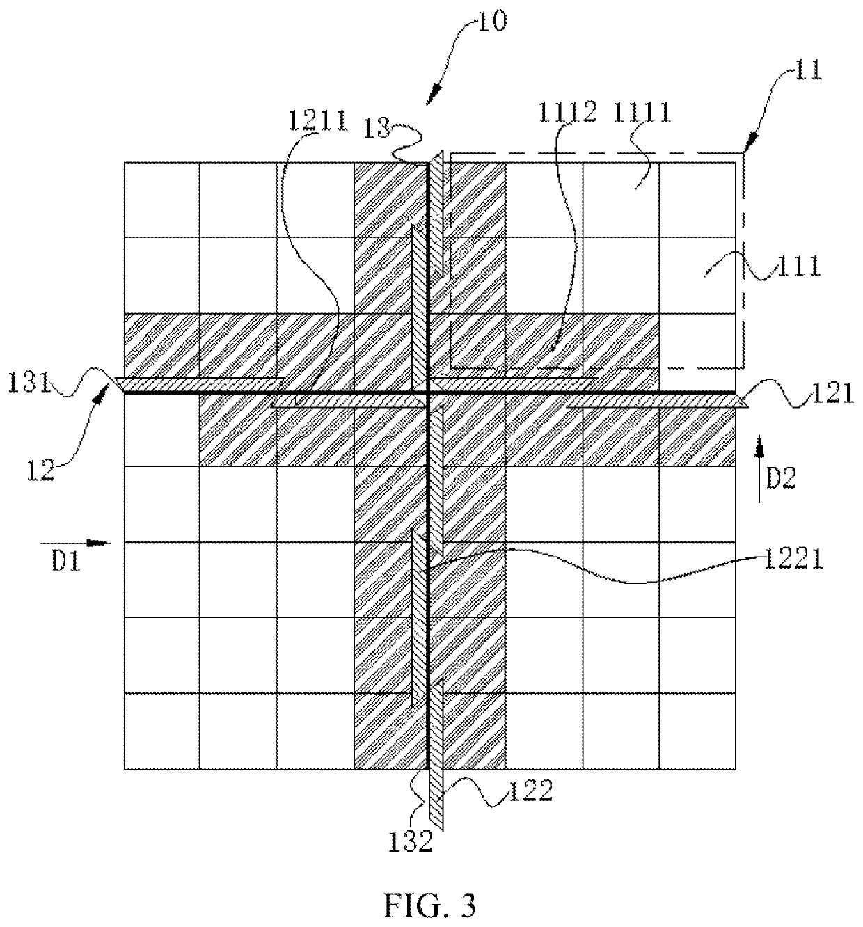
[0051]Illustrated in FIG. 3 is a structural schematic diagram of repeat units of the LED splicing display panel provided by the present disclosure. Furthermore, the LED splicing display panel includes at least one repeat unit 10. Each of the repeat unit 10 includes four sub-LED display panels spliced to each other. Display regions 11 of the four sub-LED display panels are arranged in two rows and two columns. Each of the sub-LED display panels includes the display region 11 and fan-out regions 12 respectively corresponding to two adjacent sides of the plurality of display regions 11. Slits 13 are between two adjacent sub-LED display panels. The two adjacent sub-LED display panels share the fan-out regions 12.

[0052]Specifically, sub-pixels 111 are in the four display regions 11. The sub-pixels 111 include irregular-shaped sub-pixels 1112 located on edges of the four display regions 11, and regular-shaped sub-pixels 1111 respectively being adjacent to the irregular-shaped sub-pixels 1...


PUM


Abstract

An LED splicing display panel includes at least one repeat unit. Each of the repeat unit includes four sub-LED display panels spliced to each other. Each of the sub-LED display panels includes a display region and fan-out regions. A plurality of slits are between two adjacent sub-LED display panels. The two adjacent sub-LED display panels share the plurality of fan-out regions. The plurality of sub-pixels in the four display regions include a plurality of irregular-shaped sub-pixels and a plurality of regular-shaped sub-pixels. Each of the plurality of irregular-shaped sub-pixels abuts to the corresponding fan-out region.

Description

FIELD OF INVENTION[0001]The present disclosure relates to the field of display technology, and particularly relates to a light emitting diode (LED) splicing display panel.BACKGROUND OF INVENTION[0002]Currently, light emitting diode (LED) display screens are a type of flat-panel displays, and they are constituted by a plurality of small LED module panels and used as equipment for displaying various information such as words, images, video signals, etc. High brightness, wider viewing angles, and good color recovering ability of the LED display screens are also better than liquid crystal display (LCD) screens. Having great advertising values, LED screen swiping machines are often used in airports, shopping malls, hotels, high-speed rails, subways, cinemas, exhibitions, office buildings, etc. for targeting consumers with great spending power. The current LED display screens need to be spliced to manufacture LED splicing screens during use according to specific lengths. However, the LED ...

Claims


Application Information

Patent Timeline
IPC IPC(8): G09F9/302G09F9/33H01L27/15H01L33/62
CPCG09F9/3026H01L33/62H01L27/156G09F9/33
Inventor TANG, AIHUA
Owner SHENZHEN CHINA STAR OPTOELECTRONICS SEMICON DISPLAY TECH CO LTD
Why Eureka
Try Eureka