Floor mat with damp-proof effect

Pending Publication Date: 2021-11-25
CHA YAU SPONGE ENTERPRISE
View PDF0 Cites 0 Cited by
  • Summary
  • Abstract
  • Description
  • Claims
  • Application Information

AI Technical Summary

Benefits of technology

[0006]The primary objective of the present invention is to provide a floor mat that has a damp-proof effect and therefore will

Problems solved by technology

Nevertheless, the aforesaid conventional floor mats tend to get damp after prolonged contact with the floor.
When used for a long time and mingled with the dirt in the env

Method used


Image

  • Floor mat with damp-proof effect
  • Floor mat with damp-proof effect
  • Floor mat with damp-proof effect

Examples


Example

[0016]To demonstrate the technical features of the present invention in detail, a preferred embodiment is presented below and described with reference to FIG. 1 to FIG. 7.

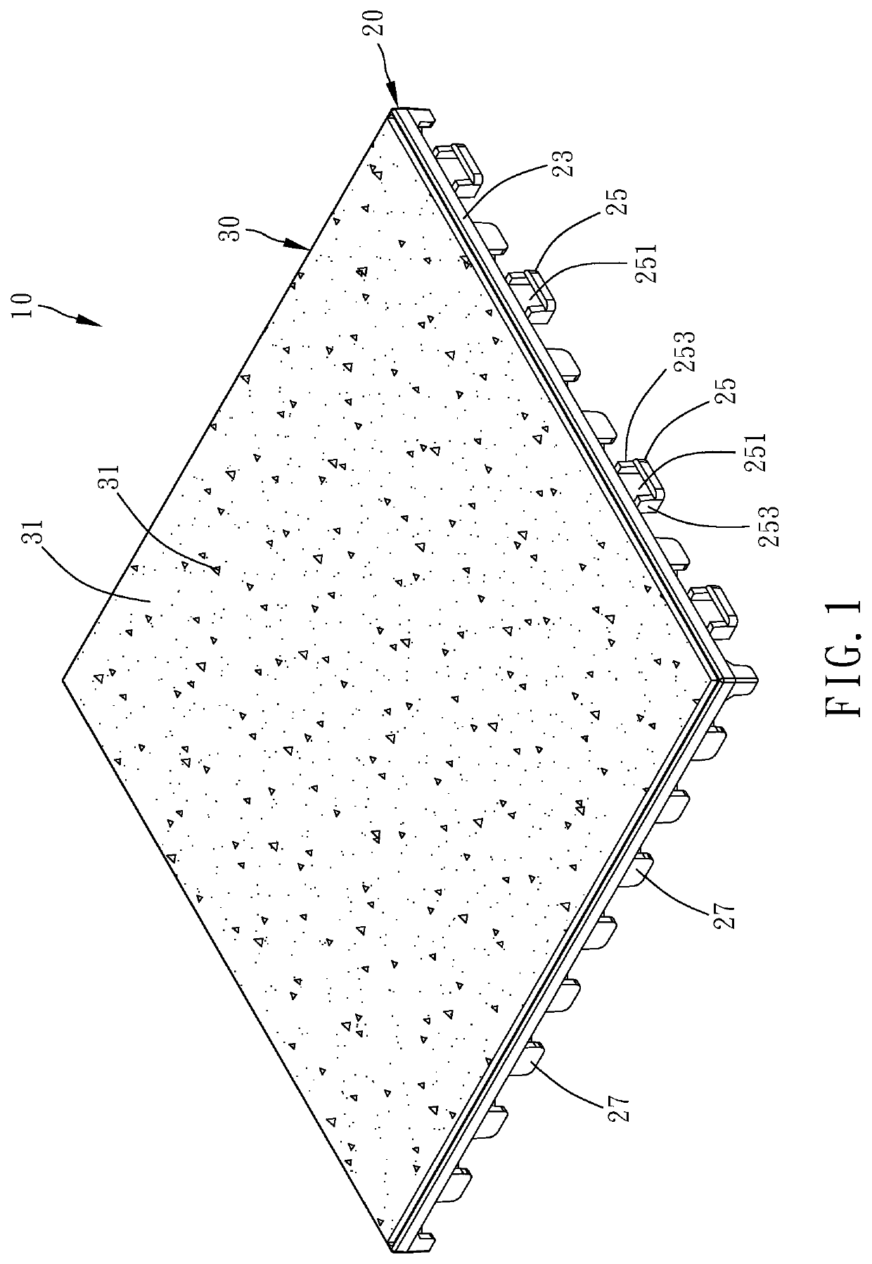
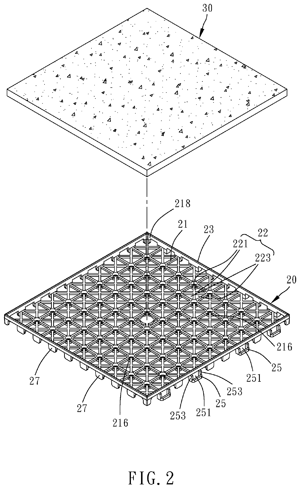
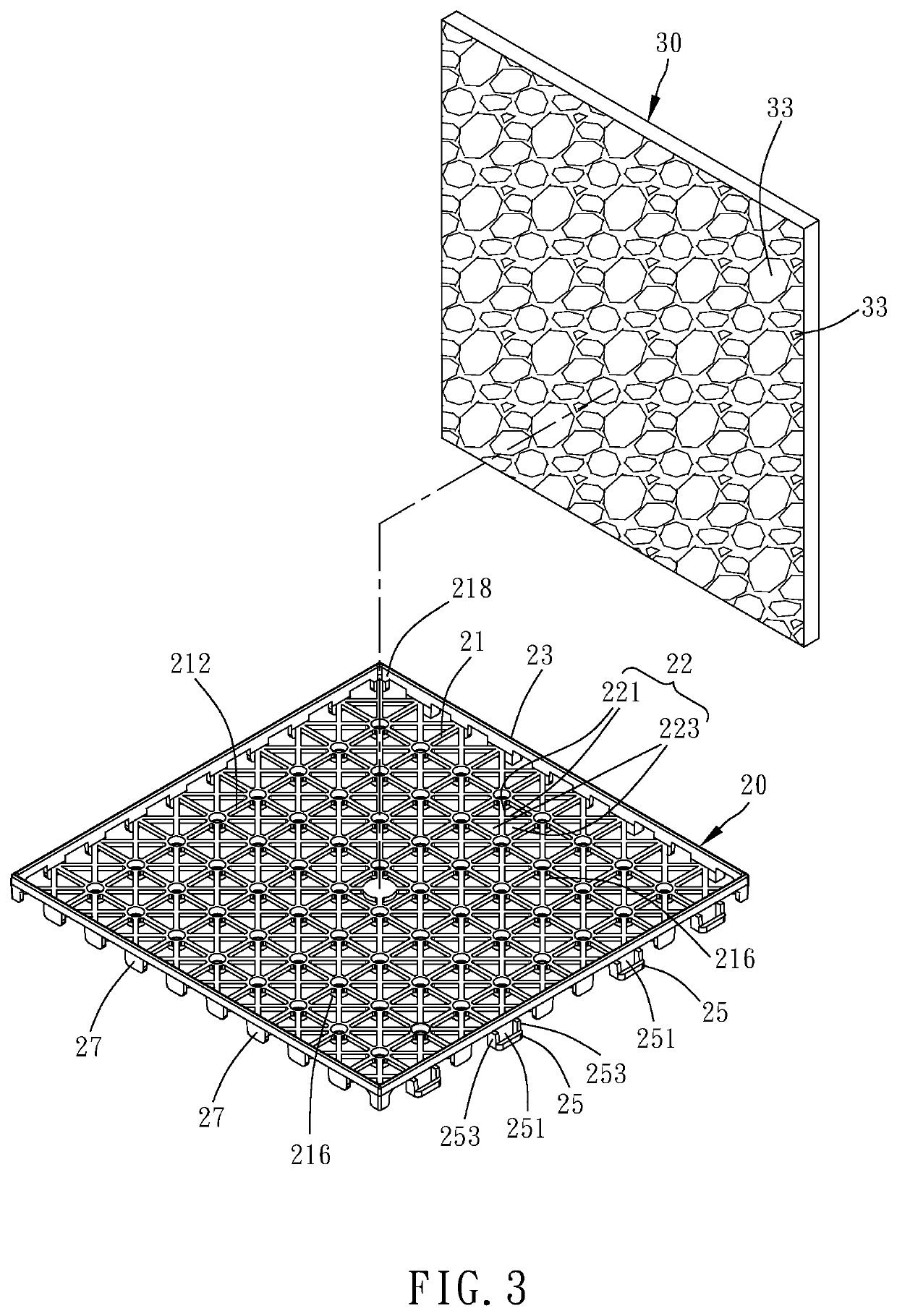
[0017]As shown in FIG. 1 to FIG. 4, a floor mat 10 with a damp-proof effect according to a preferred embodiment of the present invention is composed essentially of a base 20 and a mat portion 30.

[0018]The base 20 has a bottom plate 21, a blocking member 23, a plurality of female fasteners 25, and a plurality of male fasteners 27. The bottom plate 21 has a top side 212 and a bottom side 214. A plurality of supporting legs 216 extend downward from the bottom side 214. The supporting legs 216 are configured to stand on a predetermined object (not shown), and in this preferred embodiment the predetermined object is the floor by way of example such that the bottom plate 21 is spaced apart from the floor by a predetermined distance. The blocking member 23 is provided along the periphery of the bottom plate 21 and extends...


PUM


Abstract

A floor mat with a damp-proof effect includes a base and a mat portion. The base has a bottom plate, a blocking member, a female fastener, and a male fastener. The bottom plate has a top side and a bottom side. Plural supporting legs extend downward from the bottom side. The blocking member runs along the periphery of the bottom plate and extends upward of, and forms a receiving groove together with, the top side. The female fastener is provided on the periphery of the bottom plate and forms an opening. The male fastener is provided on the same periphery and extends downward of the bottom side. The height of the mat portion, which is detachably received in the receiving groove, is flush with or higher than the top edge of the blocking member. The floor mat will not easily get damp.

Description

BACKGROUND OF THE INVENTION1. Technical Field[0001]The present invention relates to floor mats and more particularly to a floor mat with a damp-proof effect.2. Description of Related Art[0002]Floor mats are a common product for use in our daily lives. Please refer to Taiwan Patent No. M532810, which provides a combinational mat structure having an anti-slip effect. The combinational mat is a foamed material made of ethylene-vinyl acetate (EVA), polyethylene (PE), or crosslinked polyethylene (XPE) and can be laid on the floor to provide anti-slip protection for those who have the soles of their feet in contact with the surface of the foamed material.[0003]Please also refer to Taiwan Patent No. M559135, which provides a prolonged standing-type floor mat. This floor mat essentially includes an inner layer, a surface layer, and an anti-slip layer. The inner layer may be a polyurethane (PU)-based foamed material. The surface layer may be a PU-based imitation leather mat portion. The anti...

Claims


Application Information

Patent Timeline
IPC IPC(8): A47G27/02
CPCA47G27/0293
Inventor GAO, JIAN-QUAN
Owner CHA YAU SPONGE ENTERPRISE
Why Eureka
Try Eureka