
Touch display panel and display device

Inactive Publication Date: 2021-11-25
WUHAN CHINA STAR OPTOELECTRONICS SEMICON DISPLAY TECH CO LTD
View PDF0 Cites 3 Cited by
  • Summary
  • Abstract
  • Description
  • Claims
  • Application Information

AI Technical Summary

Benefits of technology

The patent is about a new way to design a touch display panel that solves the problem of larger borders. The design has two layers, one for wiring and one for the electrodes. This results in a bigger wiring area without increasing the border.

Problems solved by technology

Therefore, it is not conducive to achieving the desired narrow border design effect.

Method used


Image

  • Touch display panel and display device
  • Touch display panel and display device
  • Touch display panel and display device

Examples


Embodiment Construction

[0048]The following text will describe embodiments of the present application in detailed. The embodiments are shown in the accompanying drawings, in which the same or similar signs represent the same or similar elements or elements with the same or similar functions from beginning to end. The following embodiments described with reference to the accompanying drawings are illustrative and are intended only to explain the present application and are not understood as limitations to the application.

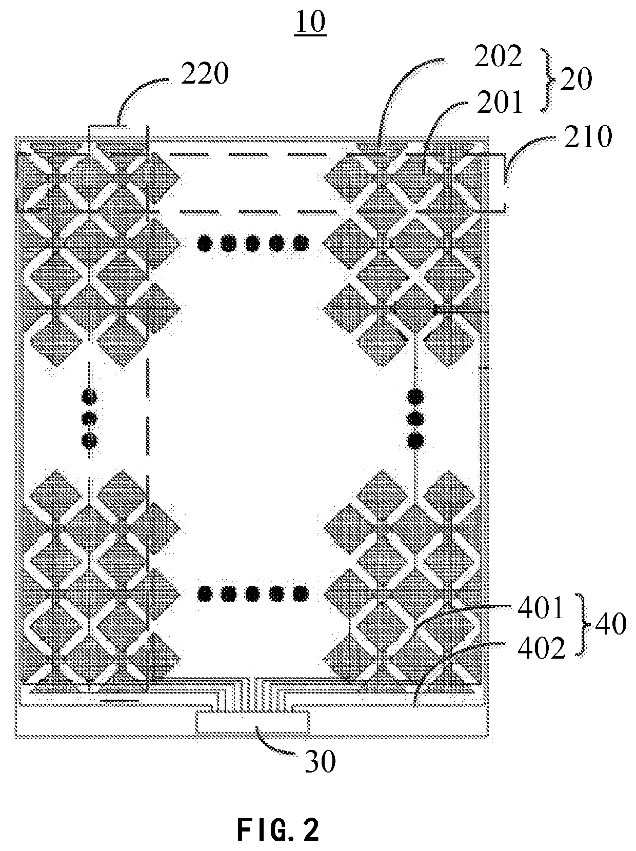
[0049]Please refer to FIG. 2, it shows a structure schematic view of a touch display panel provided in one embodiment of the present application.

[0050]The embodiment of the present application provides a touch display panel, which includes:

[0051]a substrate 10; multiple electrodes 20 disposed on the substrate 10; and a driver chip 30.

[0052]The electrode 20 is connected to the driver chip 30 by a wiring 40. Wherein, at least part of the wiring 40 and the electrode 20 are located in different...


PUM


Abstract

The present application provides a touch display panel, including a substrate, multiple electrodes disposed on the substrate, and a driver chip. The electrode is connected to the driver chip by a wiring, wherein at least part of the wiring and the electrode are located in different layers.

Description

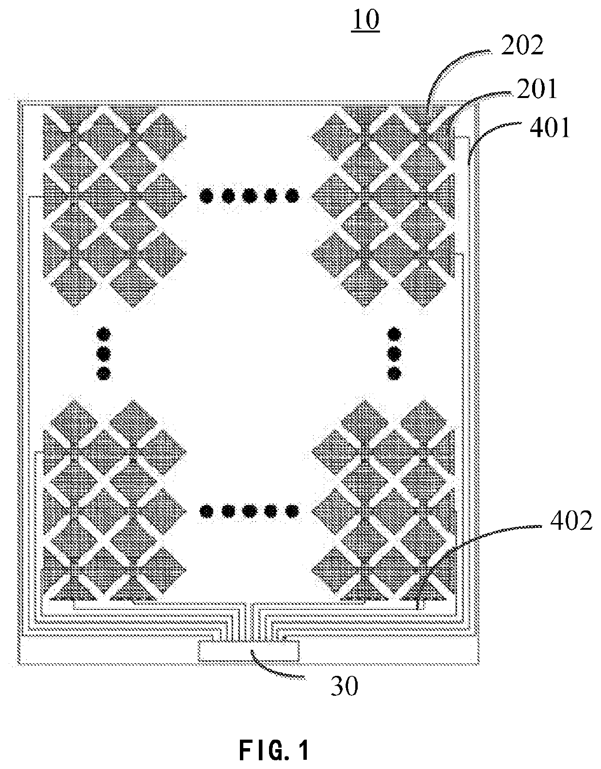
BACKGROUND OF THE INVENTION1. Field of the Invention[0001]The present application relates to a display technology field, and more particularly to a touch display panel and a display device.2. Description of the Prior Art[0002]A touch display panel is the latest computer input device. It is a simplest, convenient and natural way of human-computer interaction. As the new appearance of multimedia, it is an attractive new multimedia interactive device.[0003]Please refer to FIG. 1, it shows a structure schematic view of a touch display panel in the prior art. The prior touch display panel includes a substrate 10, multiple first electrodes 201 disposed on the substrate 10, multiple second electrodes 202 disposed on the substrate 10, and a driver chip 30. Normally, each first electrode 201 is connected to the driver chip by one first wiring 401 set outside a touch area, and each second electrode 202 is connected to the driver chip 30 by one second wiring 402 set outside the touch area.[000...

Claims


Application Information

Patent Timeline
IPC IPC(8): G06F3/044G06F3/041
CPCG06F3/0446G06F2203/04111G06F3/04164G06F3/0412G06F3/044G06F2203/04112G06F3/0443
Inventor FENG, XIAOLIANG
Owner WUHAN CHINA STAR OPTOELECTRONICS SEMICON DISPLAY TECH CO LTD
Learn More