Dynamically reconfigurable processor and processor control program for controlling the same

a processor and dynamic reconfiguration technology, applied in the direction of instruments, computation using denominational number representation, architecture with multiple processing units, etc., can solve the problem of consuming the whole wiring area of a larger area

Inactive Publication Date: 2009-08-04
RENESAS ELECTRONICS CORP
View PDF5 Cites 2 Cited by
  • Summary
  • Abstract
  • Description
  • Claims
  • Application Information

AI Technical Summary

Benefits of technology

[0010]An object of the present invention is to provide a dynamically reconfigurable processor having a wiring structure which enables flexible mapping of a program to the processor in a small wiring area and a processor control program which controls the same.
[0017]According to the present invention, a program can be flexibly mapped to a dynamically reconfigurable processor composed of nonuniform arithmetic circuit groups with small increase in the wiring area.

Problems solved by technology

In the above-described technology, however, in order to flexibly map a program to a dynamically reconfigurable processor having a nonuniform configuration composed of, for example, two types of arithmetic circuits A and B, wherein most of them are the arithmetic circuits A and the rest of them are the arithmetic circuits B which are disposed to be adjacent to each other, more wires have to be added compared with a dynamically reconfigurable processor composed of uniform arithmetic circuits, and there is a problem that a larger wiring area is consumed as a whole.

Method used


Image

  • Dynamically reconfigurable processor and processor control program for controlling the same
  • Dynamically reconfigurable processor and processor control program for controlling the same
  • Dynamically reconfigurable processor and processor control program for controlling the same

Examples


first embodiment

[0045]

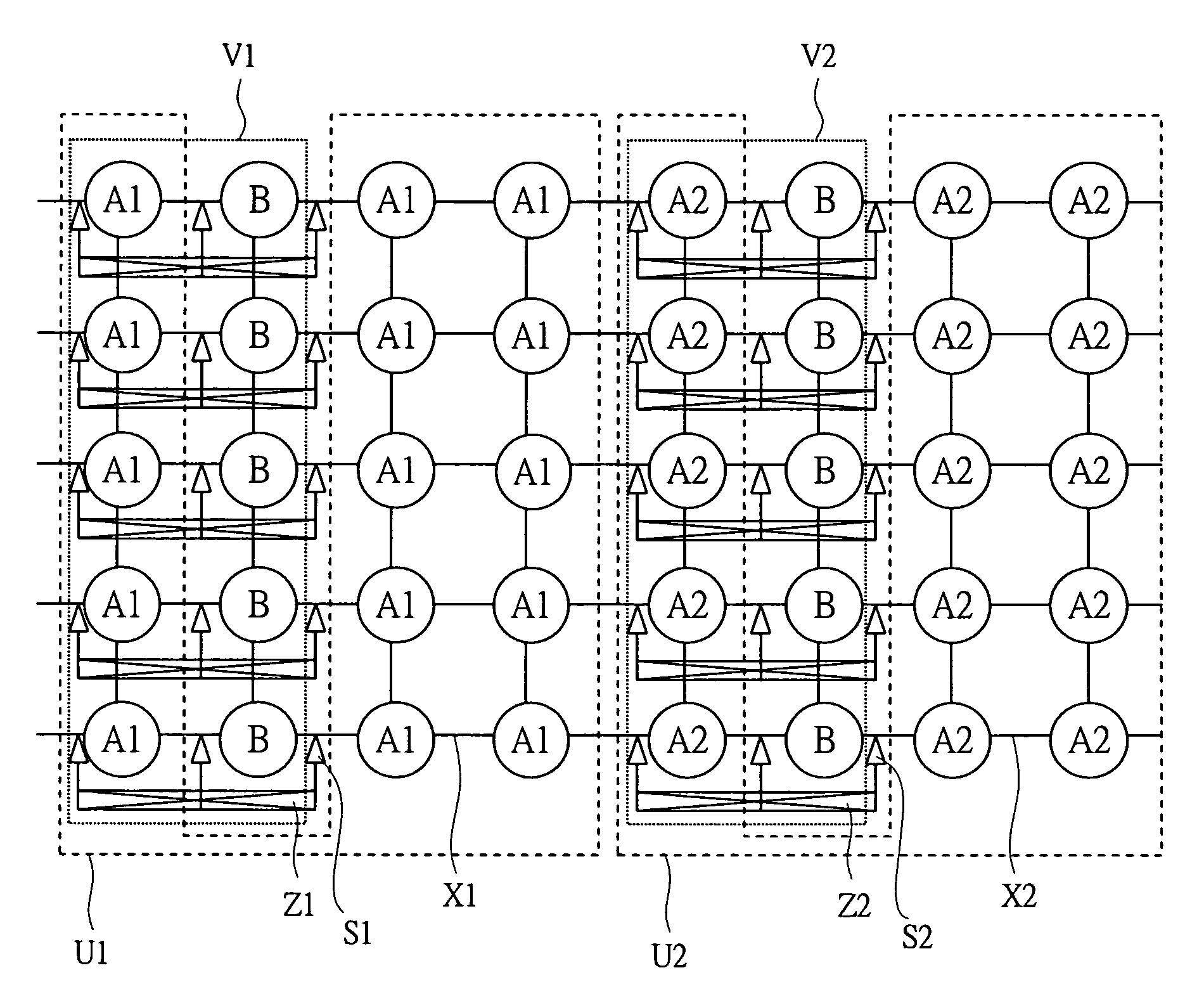
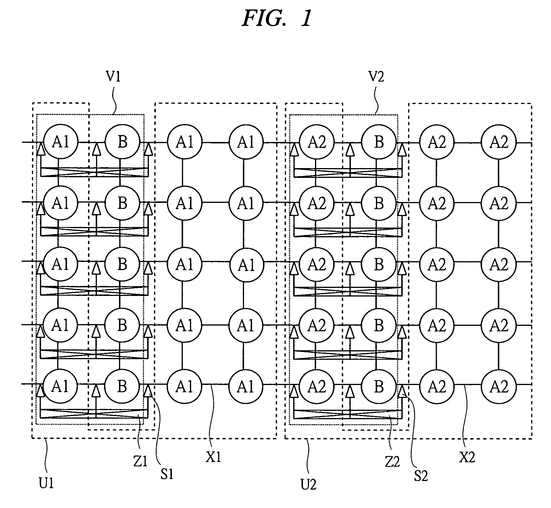
[0046]A summary of a dynamically reconfigurable processor according to a first embodiment of the present invention will be described with reference to FIG. 1. FIG. 1 is an explanatory drawing for describing the summary of the dynamically reconfigurable processor according to the first embodiment of the present invention.

[0047]In FIG. 1, Ai (i=1, 2, . . . , N) is an arithmetic circuit of a type Ai, B is an arithmetic circuit of a type B which is different from the arithmetic circuit of the type Ai, Ui is a group of some arithmetic circuits composed of the arithmetic circuits of the type Ai, Vi is a group of a part of the arithmetic circuits included in the arithmetic circuit group Ui and the arithmetic circuits of the type B connected thereto, Xi is an inter-arithmetic-circuit wire, Zi is a wire added to the inter-arithmetic-circuit wire Xi and is a wire which mutually connects the arithmetic circuits in the arithmetic circuit group Vi in an order different from that of the int...

second embodiment

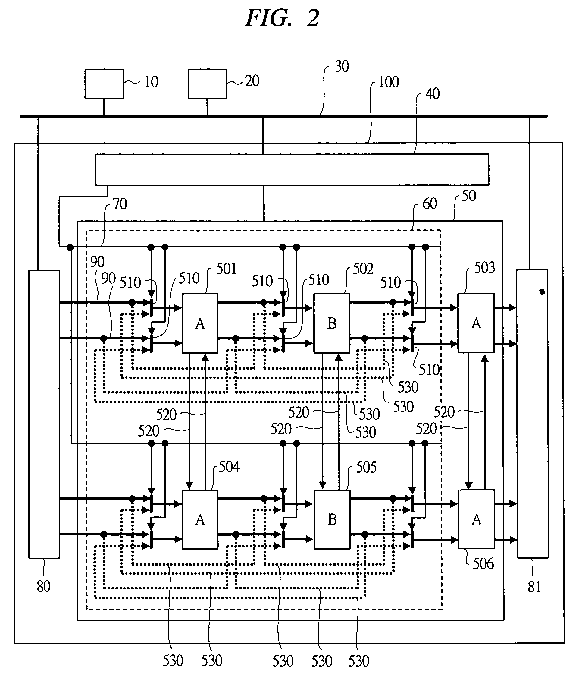
[0117]In the first embodiment, the arithmetic circuit 501 and the arithmetic circuit 502 are connected to the arithmetic circuit 504 and the arithmetic circuit 505, respectively, by the vertical wires 520. In a second embodiment, however, wires and switches are added so that the arithmetic circuit 501 can be connected to the arithmetic circuit 502 or the arithmetic circuit 505 and similarly the arithmetic circuit 503 can be connected to the arithmetic circuit 502 or the arithmetic circuit 505.

[0118]

[0119]Next, the configuration of a dynamically reconfigurable processor according to the second embodiment of the present invention will be described with reference to FIG. 18. FIG. 18 is a configuration diagram showing the configuration of the dynamically reconfigurable processor according to the second embodiment of the present invention.

[0120]First of all, the difference between FIG. 2 of the first embodiment and FIG. 18 of the second embodiment will be described.

[0121]In FIG. 2 of the...


PUM


Abstract

A dynamically reconfigurable processor is provided having a wiring structure which enables flexible mapping of a program to the processor with a small wiring area. A first wire permits a first arrangement of circuit blocks and a second wire provided for changing the arrangement order of the circuit blocks. A switch is provided to switch between the first wire and the second wire. By virtue of this arrangement, a greater variety of calculations can be performed in the circuit without the necessity for increasing the number of operation blocks.

Description

CROSS-REFERENCE TO RELATED APPLICATION[0001]The present application claims priority from Japanese Patent Application No. JP 2005-336924 filed on Nov. 22, 2005, the content of which is hereby incorporated by reference into this application.TECHNICAL FIELD OF THE INVENTION[0002]The present invention relates to a dynamically reconfigurable processor in which a configuration can be dynamically changed. More particularly, it relates to a technology effectively applied to a processor having a plurality of arithmetic circuits and a plurality of wires between the arithmetic circuits as constituent elements.BACKGROUND OF THE INVENTION[0003]Conventionally, for example, as described in Japanese Patent Application Laid-Open Publication No. 11-251442 (Patent Document 1), a reconfigurable processor device having a plurality of processing devices and a connection matrix which provides interconnection between the plurality of processing devices has been known.[0004]Also, in a conventional dynamical...

Claims


Application Information

Patent Timeline
Patent Type & Authority Patents(United States)
IPC IPC(8): G06F7/38
CPCG06F15/8007G06F15/7867
Inventor SATO, MAKOTOTSUNODA, TAKANOBUTAKADA, MASASHI
Owner RENESAS ELECTRONICS CORP
Why Eureka
Try Eureka