Holder for use in sterilisation appliances

a technology for sterilising appliances and holders, which is applied in the direction of evaporator regulation/control, biochemistry apparatus, lavatory sanitory, etc., can solve the problems of contamination of industrial systems and consequently the product that is processed in the system, and also of the production environment (premises and the like)

Pending Publication Date: 2021-12-16
MESA LABORATORY
View PDF0 Cites 0 Cited by
  • Summary
  • Abstract
  • Description
  • Claims
  • Application Information

AI Technical Summary

Benefits of technology

[0028]The object of the present invention is to provide a solution to at least one of the aforementioned and / or other disadvantages. It is an advantage of embodiments of the present invention that a holder, e.g. for holding thermocouples, biological indicators and / or other elements to be positioned in a treatment system such as for example a sterilisation system, is provided that allows accurate and reproducible positioning.
[0029]It is an advantage of at least some embodiments of the present invention that the use of these systems and methods results in higher patient safety.

Problems solved by technology

A disadvantage is that the biological indicator is easily damaged by this method of placement.
For example, ampoules can easily break, spore strips in a glassine envelope are soaked by the steam and are torn or shredded on a regular basis.
As a result, contamination of the industrial system and consequently the product that is processed in the system, but also of the production environment (premises and the like), may occur.
As a result, the industrial system is out of service for a long time, which is of course undesirable.
Moreover, any residual glue residues from the used tape can also cause contamination, with the aforementioned disadvantages as a result.
Another disadvantage is that the measurements are not always reproducible because of these amateurish placement methods in combination with ‘human error’.
Knowing that a small deviation in position with just a few millimetres can already lead to large deviations in the results, it is therefore logical that the placement can be the cause of the non-reproducibility of the results.

Method used


Image

  • Holder for use in sterilisation appliances
  • Holder for use in sterilisation appliances
  • Holder for use in sterilisation appliances

Examples


Embodiment Construction

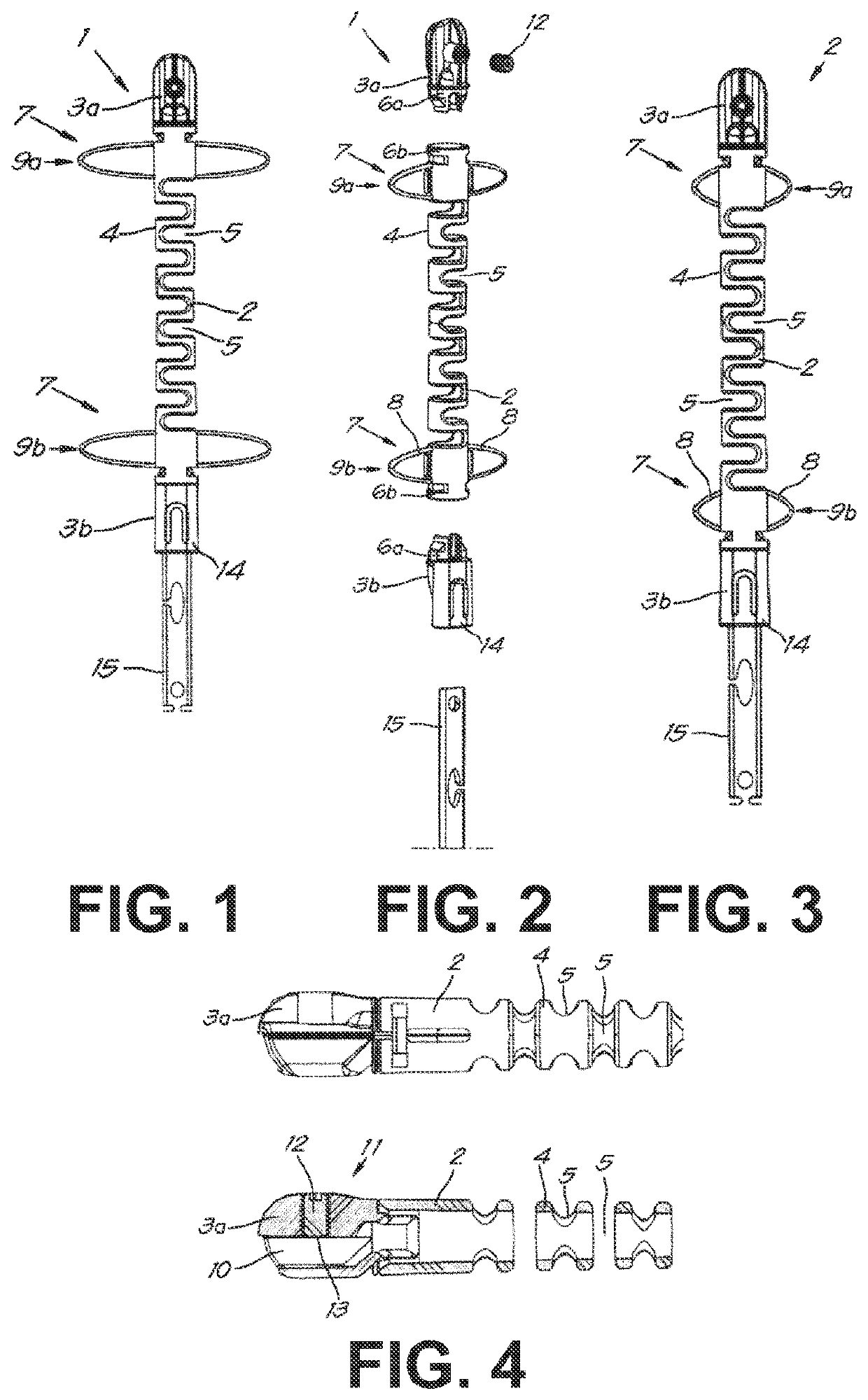
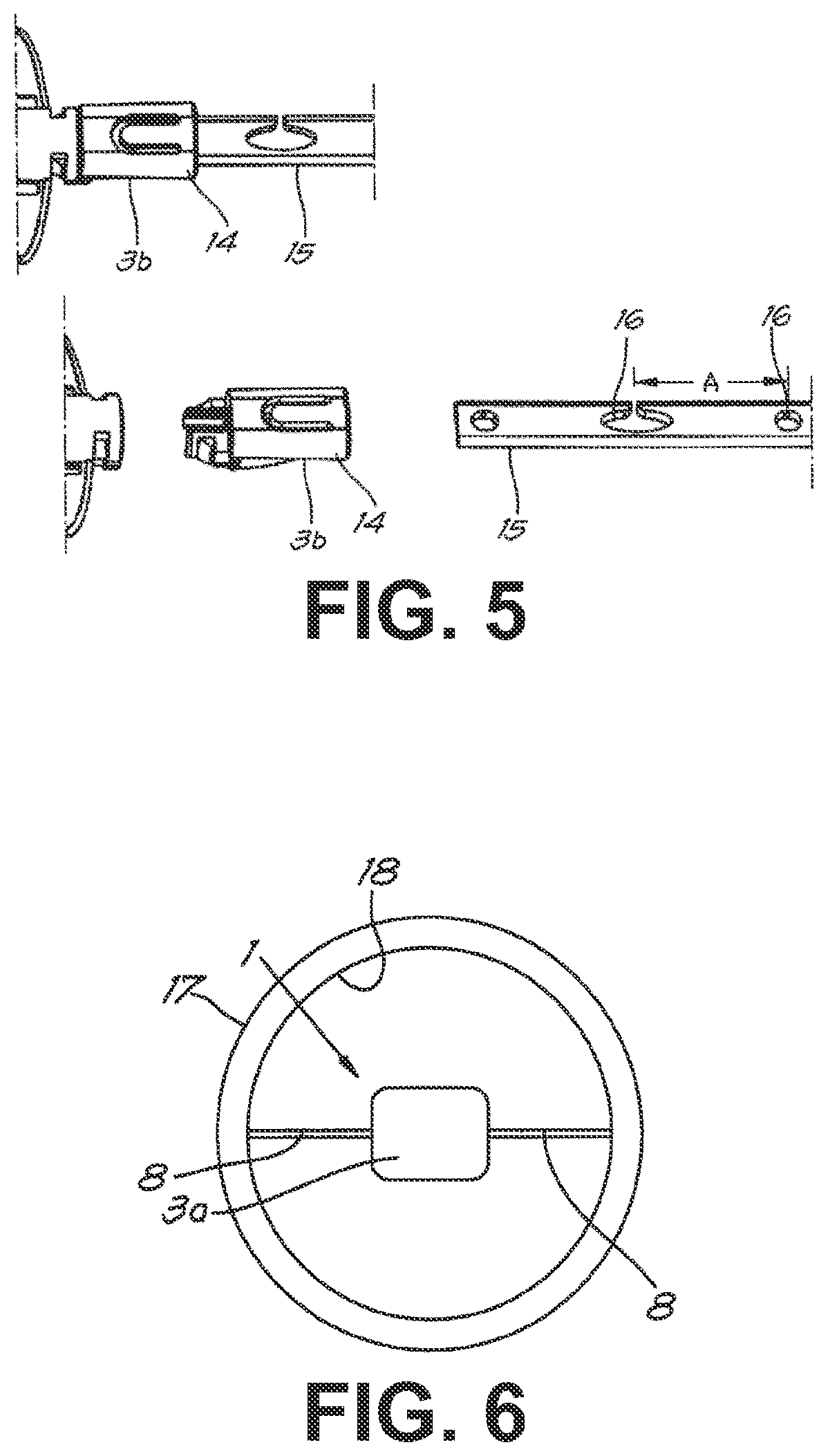
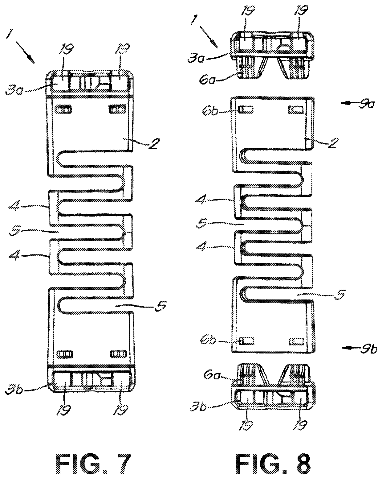
[0086]The present invention will be described with respect to particular embodiments and with reference to certain drawings but the invention is not limited thereto but only by the claims. The dimensions and the relative dimensions do not correspond to actual reductions to practice of the invention.

[0087]Furthermore, the terms first, second and the like in the description and in the claims, are used for distinguishing between similar elements and not necessarily for describing a sequence, either temporally, spatially, in ranking or in any other manner. It is to be understood that the terms so used are interchangeable under appropriate circumstances and that the embodiments of the invention described herein are capable of operation in other sequences than described or illustrated herein.

[0088]Moreover, the terms top, under and the like in the description and the claims are used for descriptive purposes and not necessarily for describing relative positions. It is to be understood that...


PUM

PropertyMeasurementUnit
diameteraaaaaaaaaa
diameteraaaaaaaaaa
diameteraaaaaaaaaa

Abstract

A holder for holding one or more biological indicators and / or one or indicators and one or more thermocouples. The holder includes one or more basic parts, being at least one first basic part where one or more biological indicators and / or one or more thermocouples can be placed in the basic part. The basic part is provided at the location where the biological indicator or indicators can be located with one or more holes. The holder is provided with means for securing the one or more thermocouples and / or biological indicators in the holder. At least one of the one or more basic parts is flexible.

Description

FIELD OF THE INVENTION[0001]The present invention relates to a holder for one or more biological indicators and one or more thermocouples.BACKGROUND OF THE INVENTION[0002]More specifically, the invention will be used during the validation / qualification testing of sterilisation processes of production or other systems in the industry and is intended to:[0003]on the one hand, protect the biological indicators[0004]on the other hand, determine the exact position of the biological indicators and / or thermocouples in the system to be sterilised, as described in the relevant validation / qualification documents, for example test script, protocol, etc.; and this with the intention of increasing the reproducibility of the measurement results.[0005]It is known that the proper functioning of some sterilisation processes of some industrial systems, such as for example a pharmaceutical installation, must be checked mandatorily and on a regular basis. This is done during the validation / qualificatio...

Claims


Application Information

Patent Timeline
Patent Type & Authority Applications(United States)
IPC IPC(8): A61L2/28C12Q1/22
CPCA61L2/28C12Q1/22C12M37/00B01D1/0082
Inventor DENAYER, IWEIN
Owner MESA LABORATORY
Why Eureka
Try Eureka