
Profiling station, profiling unit formed therefrom and profiling system

Pending Publication Date: 2021-12-16
ASMAG HLDG
View PDF1 Cites 0 Cited by
  • Summary
  • Abstract
  • Description
  • Claims
  • Application Information

AI Technical Summary

Benefits of technology

The present invention aims to solve the problems of the prior art by providing a profiling station that can create high-quality profiles with safe and flawless surface quality. The invention includes multiple profiling stations or profiling units arranged in a single pass direction, allowing for the continuous formation of a material strip into a profile. This allows users to safely and efficiently form complex profiles with high aspect ratios while ensuring optimal surface quality during the forming process.

Problems solved by technology

The disadvantage of this is that the drive speeds and the related circumferential speeds of the driven forming rollers were difficult to synchronize and the resulting therefrom, damages to the surface occurred.
A disadvantage here is that the circumferential speed of the frustum-shaped section, along its surface line, also increases with the increased diameter.
This leads to damages to the surface of the sheet metal band to be formed.

Method used


Image

  • Profiling station, profiling unit formed therefrom and profiling system
  • Profiling station, profiling unit formed therefrom and profiling system
  • Profiling station, profiling unit formed therefrom and profiling system

Examples


Embodiment Construction

[0065]First of all, it is to be noted that in the different embodiments described, equal parts are provided with equal reference numbers and / or equal component designations, where the disclosures contained in the entire description may be analogously transferred to equal parts with equal reference numbers and / or equal component designations. Moreover, the specifications of location, such as at the top, at the bottom, at the side, chosen in the description refer to the directly described and depicted figure and in case of a change of position, these specifications of location are to be analogously transferred to the new position.

[0066]The term “in particular” shall henceforth be understood to mean that it may refer to a possible more specific formation or more detailed specification of an object or a process step, but need not necessarily depict a mandatory, preferred embodiment of same or a mandatory practice.

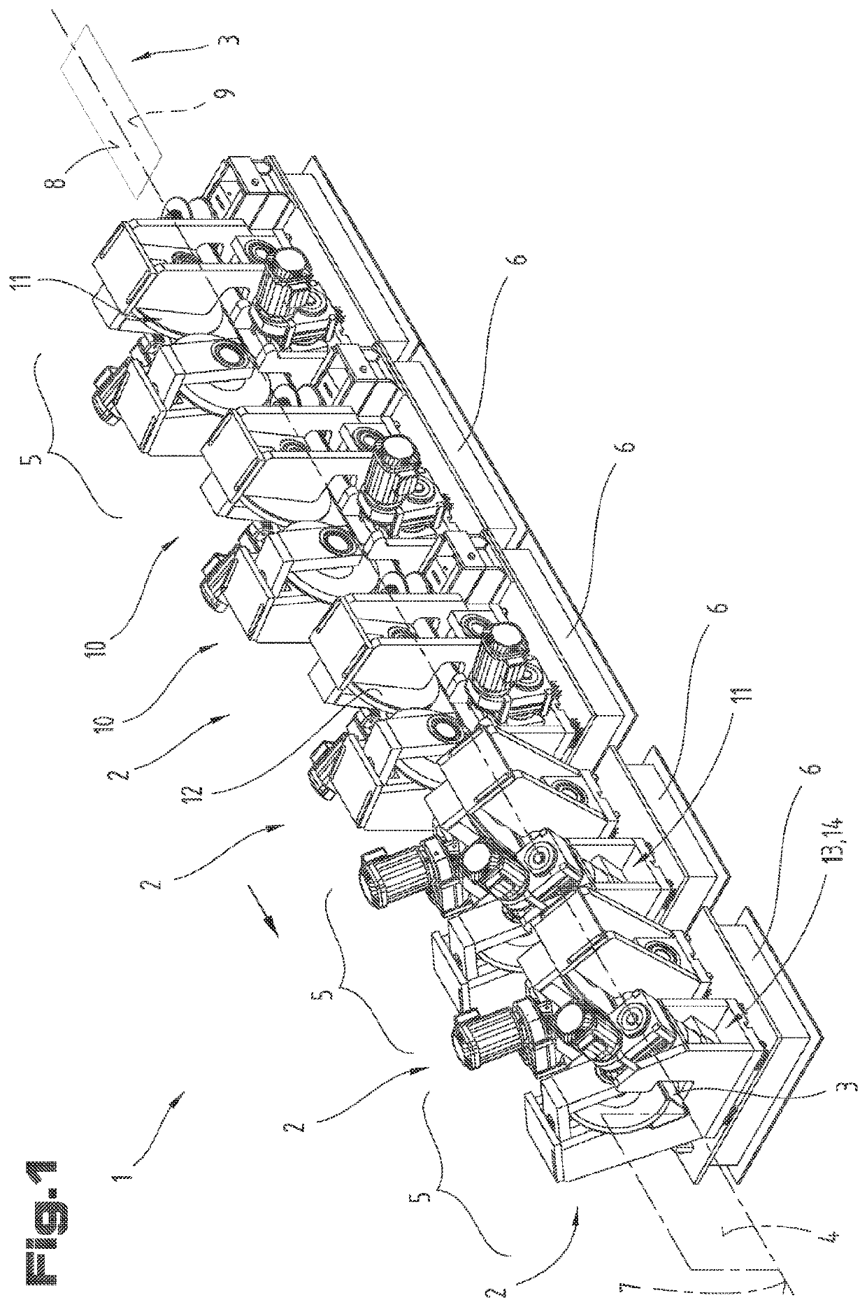
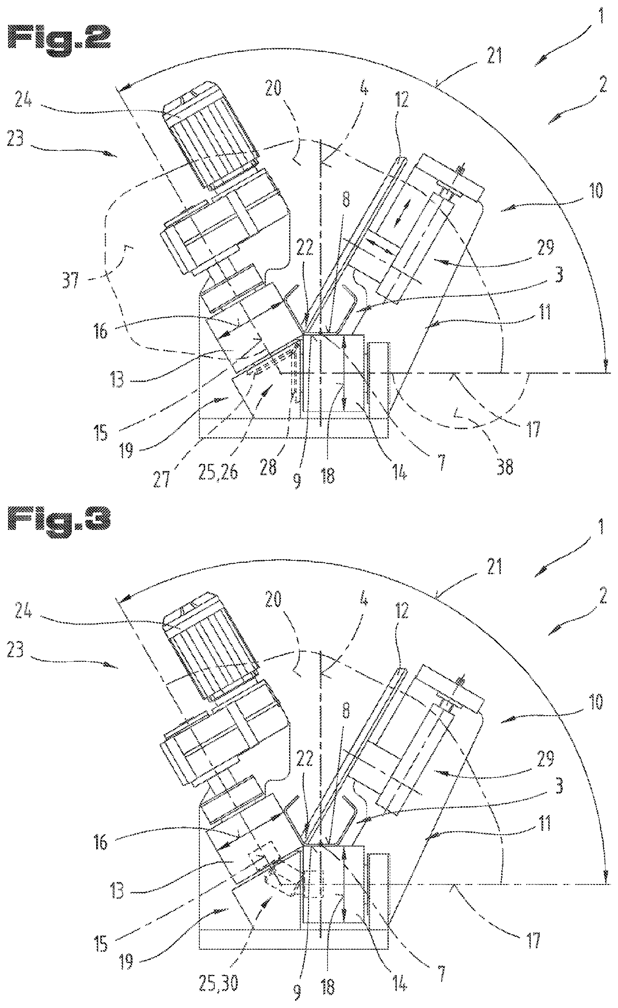
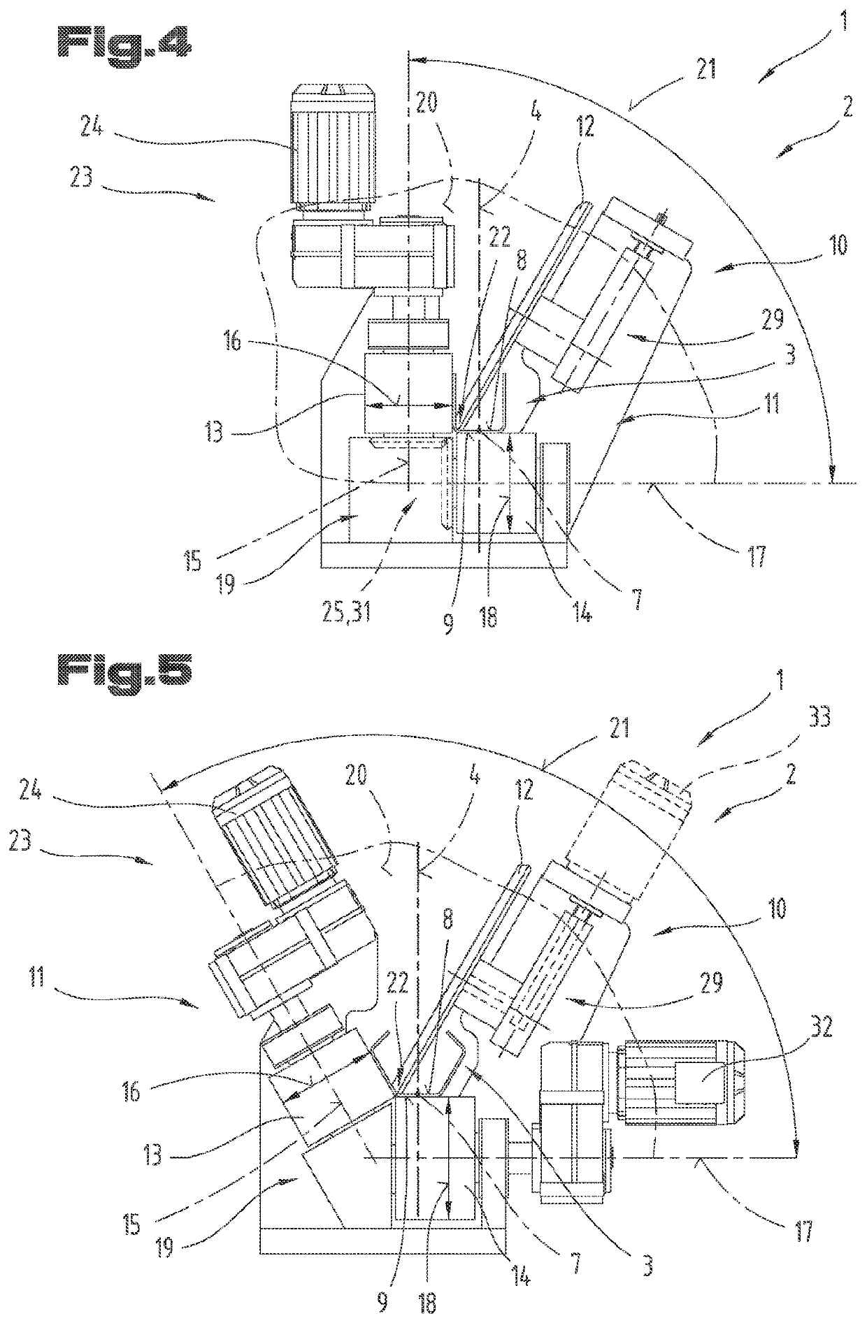
[0067]FIG. 1 shows in further detail and describes a profiling installatio...


PUM

PropertyMeasurementUnit
Angleaaaaaaaaaa
Diameteraaaaaaaaaa
Speedaaaaaaaaaa

Abstract

A profiling station, a profiling unit formed therefrom and also a profiling installation continuously form a material strip into a profile. The profiling station includes a rack frame, a profiling arrangement with a forming roller and also a first and a second counter roller as well as a drive assembly. A first roller axis and a second roller axis of the counter rollers form between them a buckling angle, wherein the counter rollers define a bending edge for the material strip to be formed. The first counter roller and also the second counter roller are driven by the drive assembly in such a way that the first counter roller has a circumferential speed at its outer circumference and the second counter roller has a circumferential speed at its outer circumference that are equal to one another.

Description

CROSS REFERENCE TO RELATED APPLICATIONS[0001]This application is the National Stage of PCT / AT2019 / 060347 filed on Oct. 18, 2019, which claims priority under 35 U.S.C. § 119 of Austrian Application No. A 50909 / 2018 filed on Oct. 19, 2018, the disclosure of which is incorporated by reference. The international application under PCT article 21(2) was not published in English.BACKGROUND OF THE INVENTION1. Field of the Invention[0002]The invention relates to a profiling station, a profiling unit each formed of two associated profiling stations, and also a profiling installation comprising multiple profiling stations and / or profiling units arranged in succession in a pass direction for the continuous forming of a material strip into a profile, in particular into a longitudinally welded profile with a rectangular cross-section.2. Description of the Related Art[0003]JP 2000 042640 A describes a forming unit for forming an elongated sheet metal part into a cross-sectional shape angled with r...

Claims


Application Information

Patent Timeline
IPC IPC(8): B21C37/08B21D5/08
CPCB21C37/0803B21D5/086B21D5/083B21D5/08
Inventor VIELHABER, JOHANNIMBERGE, MANFRED
Owner ASMAG HLDG
Learn More