Dual elastic plate connector
a technology of elastic plates and connectors, applied in the direction of coupling contact members, coupling device connections, connections effected by permanent deformation, etc., can solve the problems of insufficient connection stability, yield resistance and forward contact force, and it is difficult for such structures to meet the user's demand for transient break performance testing, etc., to improve the yield resistance of elastic plates, improve the insufficiency of combination stability, and increase the forward contact force
- Summary
- Abstract
- Description
- Claims
- Application Information
AI Technical Summary
Benefits of technology
Problems solved by technology
Method used
Image

Examples
embodiment 1
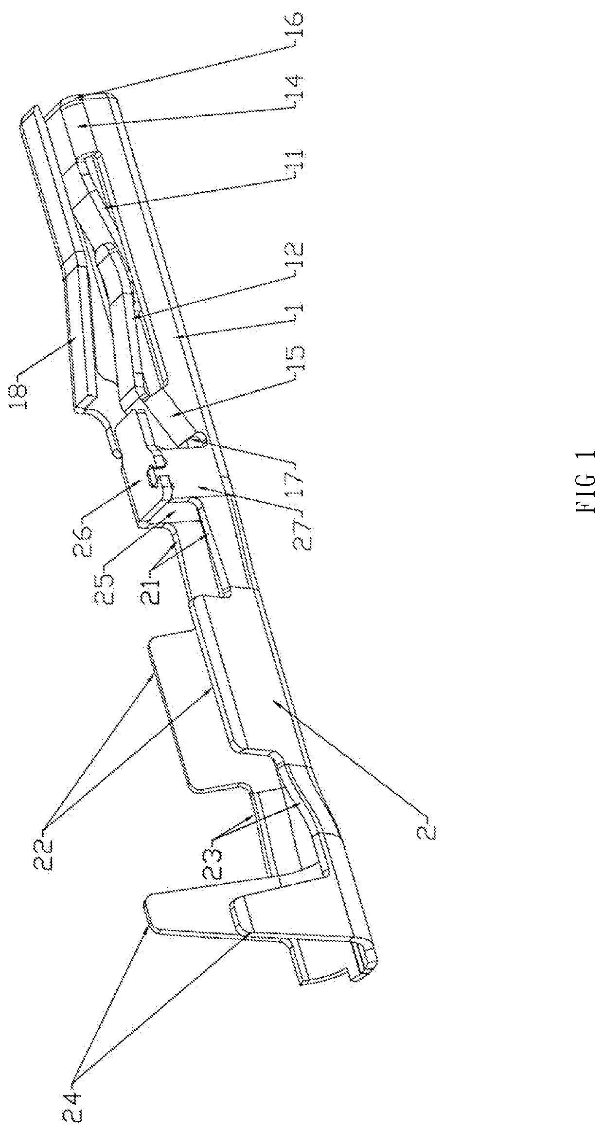
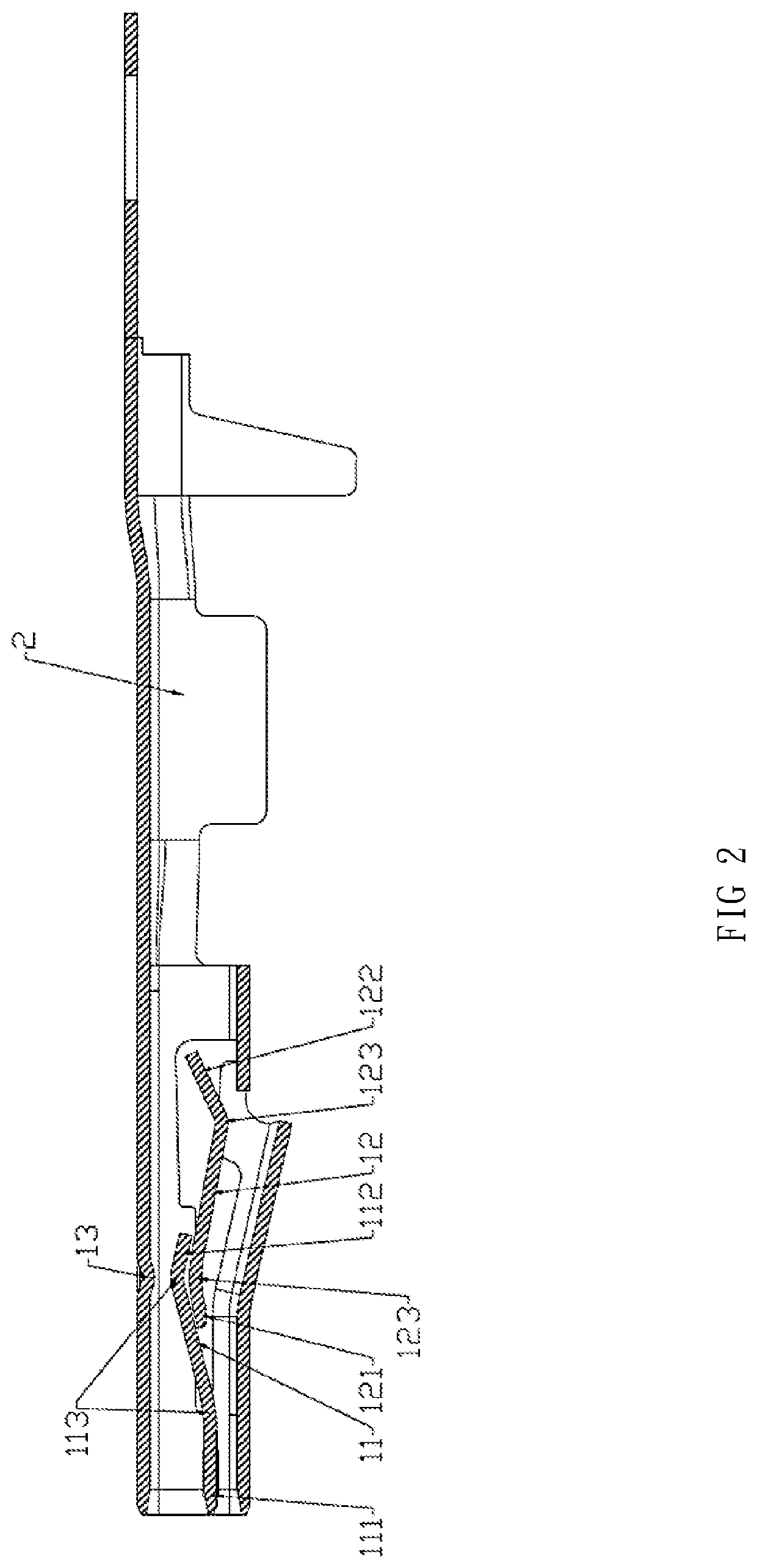
[0012]Referring to FIG. 1 and FIG. 2, a dual elastic plate connector comprises an engagement portion 1 and a combination portion 2.
[0013]The engagement portion 1 is engaged with another connector; the engagement portion includes a first elastic plate 11, a second elastic plate 12, and a protrusion part 13.
[0014]The combination portion 2 is combined with a cable
[0015]The first elastic plate 11 comprises a head portion 111 and a stem portion 112, with a curve structure 113 as a connection portion connected between the head portion 111 and the stem portion 112. The second elastic plate 12 comprises a head portion 121 and a stem portion 122, with a curve structure 123 as a connection portion connected between the head portion 121 and the stem portion 122. A bending direction of the bending structure 113 of the first elastic plate 11 is in opposite to a bending direction of the bending structure 123 of the second elastic plate 12. The stem portion 112 of the first elastic plate 11 overla...
embodiment 2
[0017]Based on the embodiment 1, referring to FIG. 1 and FIG. 2, the engagement portion 1 of the dual elastic plate connector further comprises a first curve member 14 and a second curve member 15.
[0018]An end of the first curve member 14 is connected with a lateral side of the head portion 111 of the first elastic member 11, and another end of the first curve member 14 is connected with a first engagement end 16 of the engagement portion 1. An end of the second curve member 15 is connected with a lateral side of the stem portion 122 of the second elastic member 12, and another end of the second curve member 15 is connected with a second engagement end 17 of the engagement portion 1.
embodiment 3
[0019]Based on the embodiments above, referring to FIG. 1 and FIG. 2, the engagement portion 1 comprises a curve block plate 18 disposed on an engagement end of the engagement portion 1.
[0020]The combination portion 2 comprises a plane tube 21, a square block plate 22, an expanding tube 23, a tapering block plate 24, and a wire press ring 25.
[0021]The wire press ring 25 is disposed on a junction between the combination portion 2 and the engagement portion 1 and comprises a press plate 26 and a block plate 27; the plane tube 21 is disposed between the wire press ring 25 and the square block plate 27. The square block plate 22 and the expanding tube 23 disposed at a middle portion of the combination portion 2; the square block plate 22 is positioned between the plane tube 21 and the expanding tube 23. The tapering block plate 24 is disposed on an end part of the combination portion 2.
PUM
 Abstract
Description
Claims
Application Information
 - R&D
- Intellectual Property
- Life Sciences
- Materials
- Tech Scout
- Unparalleled Data Quality
- Higher Quality Content
- 60% Fewer Hallucinations
Browse by: Latest US Patents, China's latest patents, Technical Efficacy Thesaurus, Application Domain, Technology Topic, Popular Technical Reports.
© 2025 PatSnap. All rights reserved.Legal|Privacy policy|Modern Slavery Act Transparency Statement|Sitemap|About US| Contact US: help@patsnap.com