
Electric brake system

a technology of electric brakes and brake pads, applied in the direction of braking systems, mechanical control devices, instruments, etc., can solve the problems of large problems, inability to stably generate hydraulic pressure for braking, and inability to ensure the safety of passengers, so as to achieve effective braking

Pending Publication Date: 2021-12-30
HL MANDO CORP
View PDF15 Cites 1 Cited by
  • Summary
  • Abstract
  • Description
  • Claims
  • Application Information

AI Technical Summary

Benefits of technology

The patent describes an electronic brake system that can work well in different situations and is more reliable and flexible than other systems. This makes it easier to design vehicles that have improved performance and flexibility.

Problems solved by technology

Although such an electronic brake system and operation method are electrically operated and controlled so that complex and various braking operations may be implemented, when a technical problem occurs in an electric component, a hydraulic pressure required for braking may not be stably generated, and thus the safety of passengers may not be secured.
In an electronic brake system, since most of the components thereof are controlled by electrical signals of an electronic control unit (ECU), a failure of the ECU may cause a great problem.
On the other hand, a failure occurs in one ECU operating in a normal mode and the moment before other ECUs that recognizes it operates, an electronic brake system operates in an abnormal operation mode in which there is no electrical signal temporarily, and may cause discomfort, such as a kickback, to the driver's pedal feeling when switching modes.

Method used


Image

  • Electric brake system
  • Electric brake system
  • Electric brake system

Examples


first embodiment

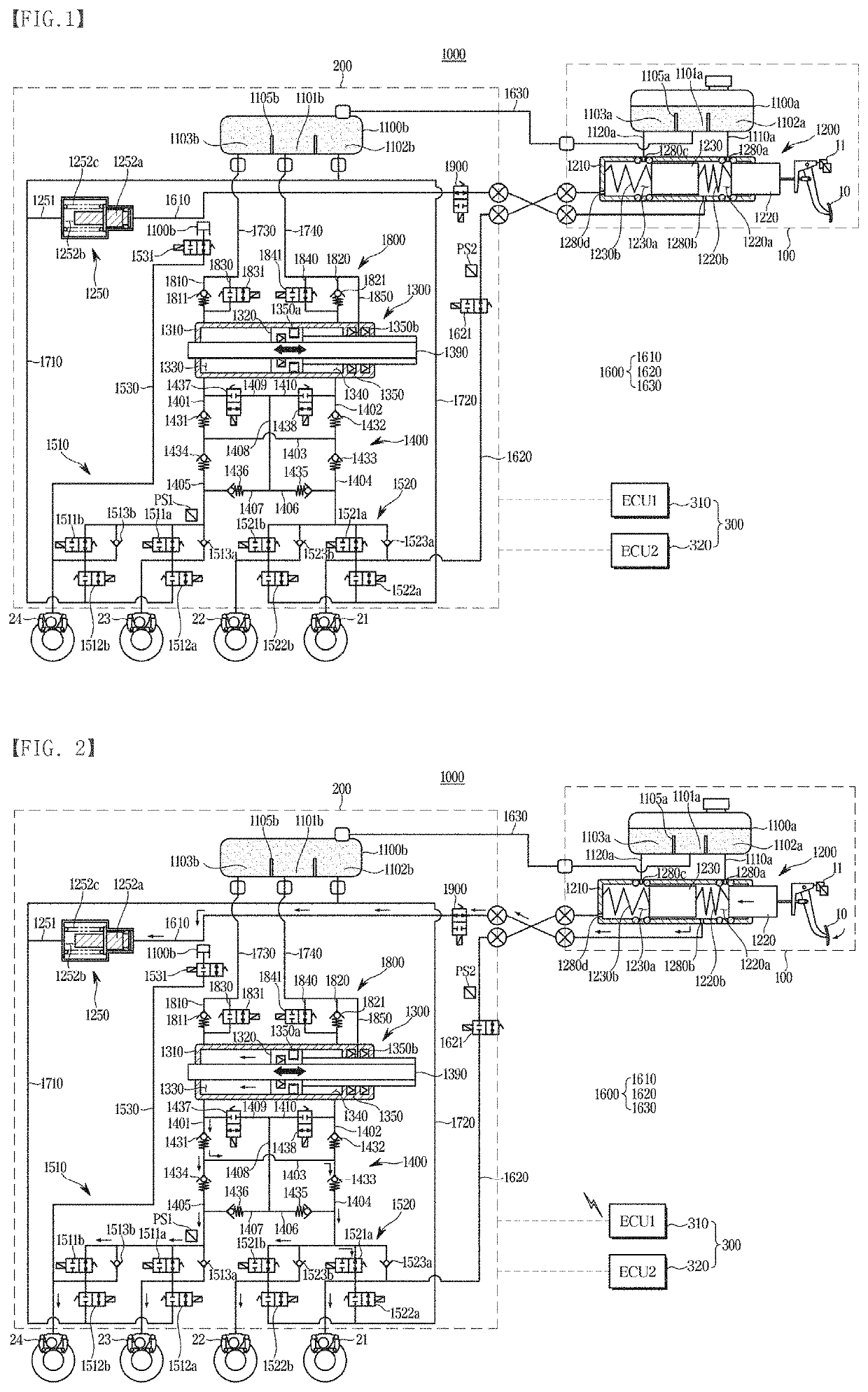
[0045]FIG. 1 is a hydraulic circuit diagram showing an electronic brake system 1000 according to the disclosure.

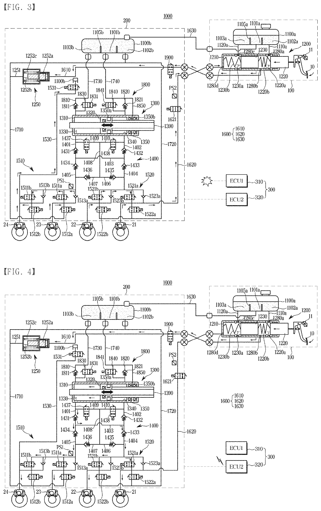
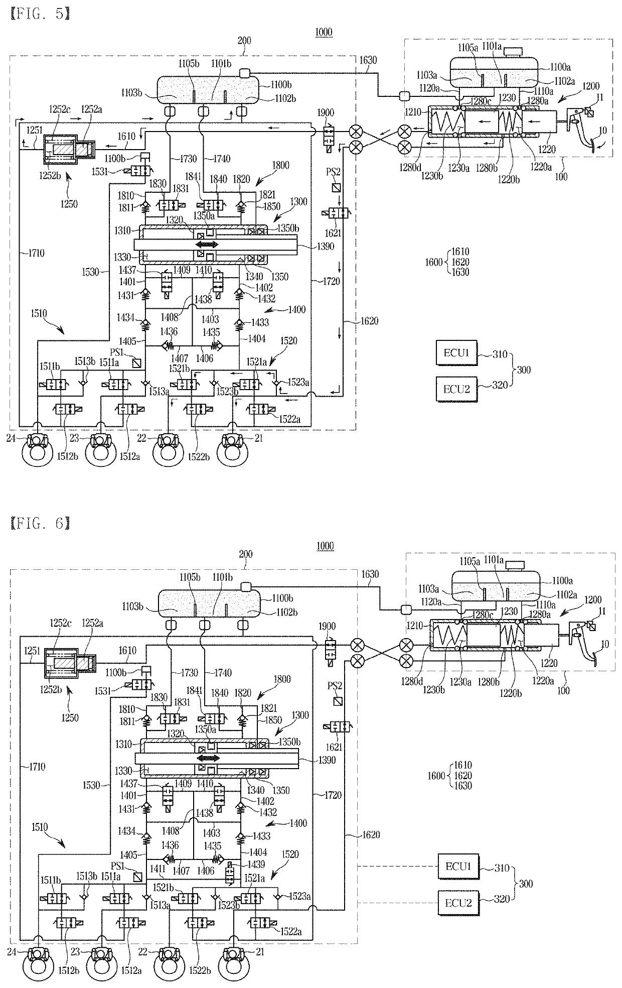
[0046]Referring to FIG. 1, the electronic brake system 1000 according to the first embodiment of the disclosure may include a first block 100 including a master cylinder 1200, a second block 200 including a pedal simulator 1250, a hydraulic pressure supply device 1300, and a hydraulic control unit 1400 and spaced apart from the first block 100, a plurality of electronic control units (ECUs) 300, and a connection line 1600 having one end connected to the first block 100 and the other end connected to the second block 200.

[0047]The first block 100 includes a mechanical unit connected and interworked with a brake pedal 10 to provide a mechanical operation, and the second block 200 includes an electrical unit electronically operated and controlled such as a valve and a sensor whose operation is controlled by an ECU 300. The first block 100 and the second block 200 are disposed...

second embodiment

[0171]Hereinafter, an electronic brake system 2000 according to the disclosure will be described.

[0172]FIG. 7 is a hydraulic circuit diagram illustrating an electronic brake system 2000 according to a second embodiment of the disclosure.

[0173]Referring to FIG. 7, the electronic brake system 2000 according to the second embodiment of the disclosure includes the first block 100 including a master cylinder 2200, the second block 200 including a pedal simulator 2250, the hydraulic pressure supply device 1300, and the hydraulic control unit 1400 and spaced apart from the first block 100, the plurality of electronic control units (ECUs) 300, and the connection lines 1600 having one end connected to the first block 100 and the other end connected to the second block 200.

[0174]The description of the electronic brake system 2000 according to the second embodiment of the disclosure to be described below is the same as the description of the electronic brake system 1000 according to the first ...


PUM


Abstract

Disclosed herein an electronic brake system includes a first block comprising a master cylinder having a first master piston connected to a brake pedal and a first master chamber whose volume is changed by a displacement of the first master piston; a second block comprising a pedal simulator, a hydraulic pressure supply device that generates a hydraulic pressure by operating a hydraulic piston according to an electrical signal, and a hydraulic control unit comprising a first hydraulic circuit that controls a hydraulic pressure transferred to two wheel cylinders and a second hydraulic circuit that controls a hydraulic pressure transferred to the other two wheel cylinders, the second block disposed to be spaced apart from the first block; a plurality of electronic control units (ECUs) that controls various devices and valves based on hydraulic pressure information and displacement information of the brake pedal; and a connection line having one end connected to the first block and the other end connected to the second block; wherein the connection line has one end connected to the first master chamber and the other end thereof connected to the pedal simulator side.

Description

CROSS-REFERENCE TO RELATED APPLICATION(S)[0001]This application is based on and claims priority under 35 U.S.C. § 119 to Korean Patent Applications No. 10-2020-0077649, filed on Jun. 25, 2020 and No. 10-2021-0082153, filed on Jun. 24, 2021 in the Korean Intellectual Property Office, the disclosure of which is incorporated herein by reference in its entirety.BACKGROUND1. Technical Field[0002]The disclosure relates to an electronic brake system, and more particularly, to an electronic brake system for improving a pedal feel and reducing occurrence of a kickback.2. Description of the Related Art[0003]Vehicles are essentially equipped with a brake system for performing braking, and various types of brake systems have been proposed for the safety of drivers and passengers.[0004]In a conventional brake system, a method of supplying a hydraulic pressure required for braking to wheel cylinders using a mechanically connected booster when a driver depresses a brake pedal has been mainly used....

Claims


Application Information

Patent Timeline
Patent Type & Authority Applications(United States)
IPC IPC(8): B60T13/68B60T8/40B60T7/04B60T13/16B60T17/06B60T17/04B60T7/06G05G1/40B60T8/88
CPCB60T13/686B60T8/4081B60T7/042B60T13/161B60T17/06B60T17/04B60T2270/402G05G1/40B60T8/885B60T2270/82B60T2270/403B60T2270/404B60T7/06B60T13/146B60T17/22B60T13/745
Inventor JUNG, HEECHUL
Owner HL MANDO CORP
Learn More