
Assist device

a technology of a tilt angle and a splint, which is applied in the field of splint devices, can solve the problems of user discomfort and increased burden on the hips of users, and achieve the effect of accurately obtaining the tilt angle information and reducing the likelihood of user injury

Inactive Publication Date: 2022-01-06
JTEKT CORP
View PDF0 Cites 0 Cited by
  • Summary
  • Abstract
  • Description
  • Claims
  • Application Information

AI Technical Summary

Benefits of technology

The disclosed assist device can reduce the discomfort felt by the user by taking into account the angles formed by the user's upper body and thighs, as well as the tilt angle of the user's upper body. By controlling the actuator to generate no or small assist torque based on the tilt angle, the user is less likely to feel discomfort. Additionally, the controller can adjust the correction gain based on the tilt angle to further relieve the burden on the user's hips. The device can accurately detect the tilt angle and swing angles using sensors, resulting in improved assist efficiency. Thus, this assist device can provide a comfortable and efficient assist to users.

Problems solved by technology

As a result, the assist device generates assist torque and may thereby cause the user to have a feeling of discomfort.
The larger the tilt angle of the upper body of the user is, the greater the burden on the hips of the user tends to be.

Method used


Image

  • Assist device
  • Assist device
  • Assist device

Examples


Embodiment Construction

[0031]Overall Structure of Assist Device

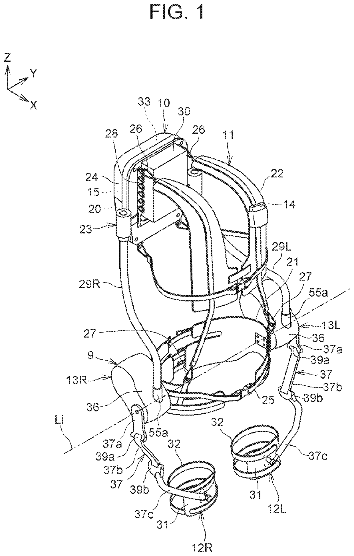
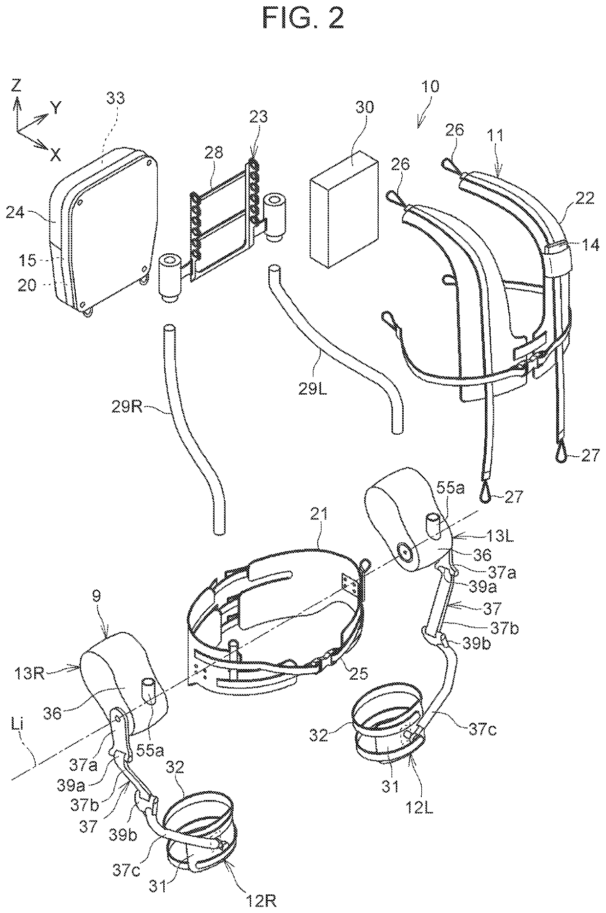
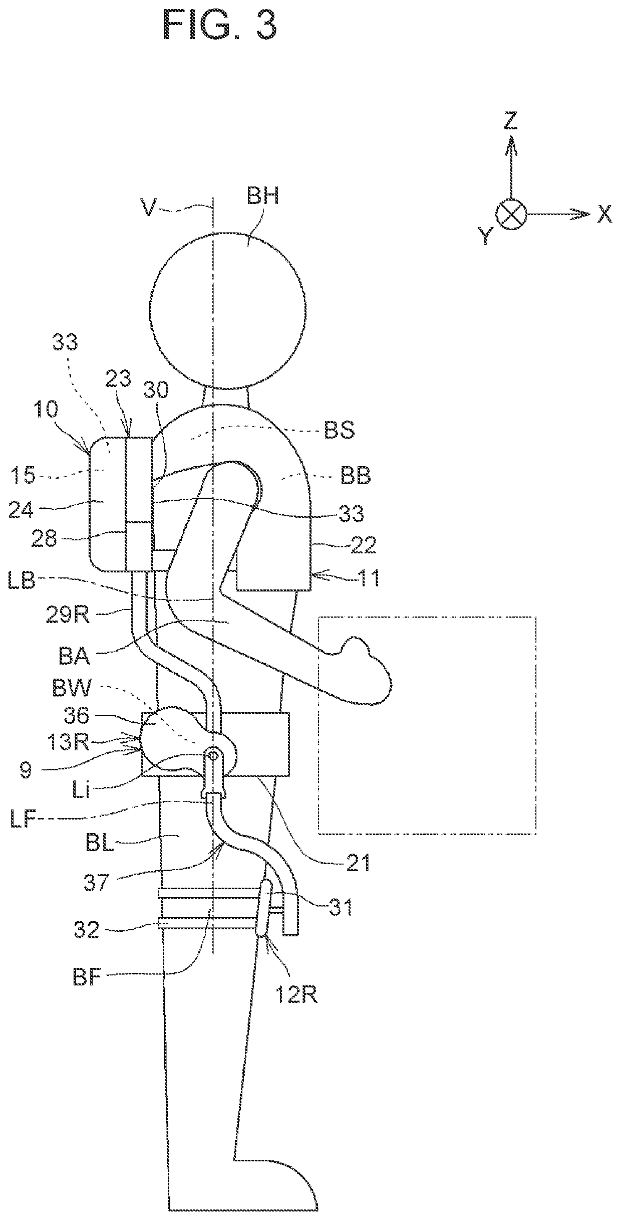
[0032]FIG. 1 is a perspective view showing the overall configuration of one example of an assist device. FIG. 2 is an exploded perspective view of the assist device shown in FIG. 1. FIG. 3 and FIG. 4 are side views showing a user wearing the assist device shown in FIG. 1. In FIG. 3, the user is in an upright standing posture, and in FIG. 4, the user is in a forward leaning posture. The upright standing posture shown in FIG. 3 is a posture in which a longitudinal direction of the body of the user from his or her leg BL to his or her head BH extends along a vertical line V The forward leaning posture shown in FIG. 4 is a posture in which a longitudinal direction of the upper body of the user from his or her hips BW to his or her head BH tilts toward a front side relatively to the vertical line V The forward leaning posture shown in FIG. 4 is a posture of the user in a state of having bent his or her legs BL at the knees. In FIG. 4, the angle of ...


PUM


Abstract

An assist device includes a first body-worn unit; second body-worn units; an actuator; a controller configured to obtain an assist parameter that determines assist torque to be generated, and perform control to operate the actuator at an output based on the assist parameter; and a tilt angle detection part configured to obtain tilt angle information on a tilt angle of an upper body of a user. The actuator includes arms; and swing angle detection parts configured to obtain swing angle information on swing angles of the arms that represent angles formed by the upper body and thighs of the user. The controller is configured to obtain the assist parameter based on the swing angle information and the tilt angle information.

Description

CROSS-REFERENCE TO RELATED APPLICATION[0001]This application claims priority to Japanese Patent Application No. 2020-116201 filed on Jul. 6, 2020, incorporated herein by reference in its entirety.BACKGROUND1. Technical Field[0002]This disclosure relates to an assist device.2. Description of Related Art[0003]Various assist devices that are worn on the bodies of users (persons) to assist the users in tasks have been proposed. When lifting a heavy object, for example, a user of an assist device can perform the task with a smaller force (with less burden). One such assist device is disclosed in Japanese Unexamined Patent Application Publication No. 2019-206045 (JP 2019-206045 A). This device includes a first body-worn unit that is worn on the upper body of a user including his or her hips, second body-worn units that are worn on the right and left legs of the user, an actuator that generates assist torque for assisting the user in moving his or her hips relatively to his or her thighs a...

Claims


Application Information

Patent Timeline
IPC IPC(8): A61H3/00A61H1/02
CPCA61H3/00A61H1/0244A61H2201/5069A61H2201/5007A61H2201/5061A61H2201/1652B25J9/0006B25J9/1602A61H2201/0157A61H2201/5084A61H2201/1215A61H2205/088A61H2201/1628A61H2201/164A61H2003/007B25J9/1633G05B2219/40305
Inventor YOSHIMI, YOSHITAKA
Owner JTEKT CORP
Learn More