Eureka AIR delivers breakthrough ideas for toughest innovation challenges, trusted by R&D personnel around the world.

Method and device for transmitting a message

Pending Publication Date: 2022-01-06
SAGEMCOM ENERGY & TELECOM
View PDF0 Cites 1 Cited by
  • Summary
  • Abstract
  • Description
  • Claims
  • Application Information

AI Technical Summary

Benefits of technology

This patent describes a way to send a message over multiple frequency bands. This helps to use the strengths of each band for better transmission, resulting in faster data transfer and better resistance to interference. This method can benefit many exchanges in the network, ultimately increasing capacity.

Problems solved by technology

Thus, when in a communication network it is necessary to reconfigure, in a new frequency band, a set of data concentrator devices and a set of electricity meters that are associated therewith, a reconfiguration may prove to be particularly complex.
For example, a meter device that has not been able to receive a message indicating to it to change frequency band may become incapable of communicating with the data concentrator device with which it is associated, after the latter, for its part, has been able to change frequency band.
The frequency band for which the elements constituting a network have been certified may be at the limit of their capacity, which does not make it possible to increase the number of exchanges in the network, for example to introduce new functionalities, new application requirements, etc.

Method used


Image

  • Method and device for transmitting a message
  • Method and device for transmitting a message
  • Method and device for transmitting a message

Examples


Embodiment Construction

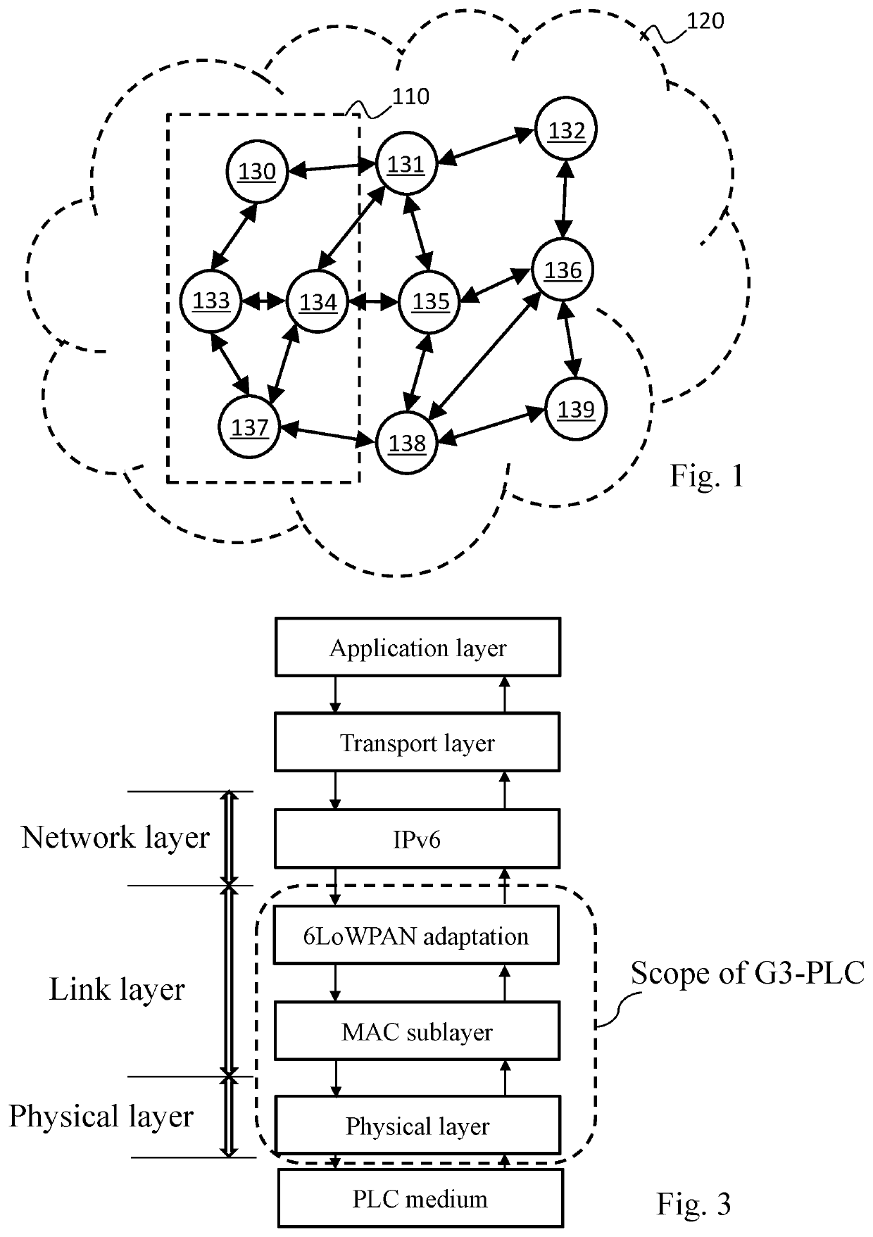
[0039]FIG. 1 illustrates schematically a mesh communication network 120. The mesh communication network 120 is for example an electrical supply network of the AMM type. The mesh communication network 120 relies on powerline communications PLC to enable a base node device (also called a “data concentrator”) to collect, from smart electricity meters, energy consumption reading data from electrical installations that said smart electricity meters are respectively responsible for monitoring. The data concentrator and the smart electricity meters are thus node devices of the mesh communication network 120. The mesh communication network 120 may comprise other node devices, for example installed at electrical transformers. The communication network 120 therefore has a mesh structure, as shown schematically on FIG. 1 by means of arrows, where node devices fulfil the role of relays for increasing the range of the communications in the mesh communication network 120, as detailed hereinafter....


PUM


Abstract

A method for transmitting a message from a first node device to a second node device in which the second node device belongs to network neighborhood of the first node device. The first and second node devices belong to an electrical supply network using powerline communications. The first node device begins by fragmenting the message into at least a first fragment and a second fragment. Next it associates a first frequency band of a set of frequency bands with the first fragment and a second frequency band with the second fragment, the first and second frequency bands being different. It then transmits each first and second fragment on the frequency band with which it is associated.

Description

TECHNICAL FIELD[0001]At least one embodiment relates to a method for transmitting a message from a first node device to a second node device belonging to a network neighbourhood of the first node device, said first and second node devices belonging to an electrical supply network using powerline communications. At least one embodiment relates to a device implementing the method.PRIOR ART[0002]Powerline communications (PLC) are developing, in particular in the context of electrical supply networks of the AMM (abbreviation signifying “Automated Meter Management”) type. Communication networks are thus implemented in electrical supply networks for the automated collection, by a base node device (also called a “data concentrator”) of the network, from smart electricity meters, of energy consumption reading data that said smart electricity meters are respectively responsible for monitoring.[0003]The G3-PLC communication standard is defined to enable the various node devices (in particular...

Claims


Application Information

Patent Timeline
IPC IPC(8): H04B3/54H04B3/38H04B1/00H04B1/7156
CPCH04B3/542H04B1/7156H04B1/0075H04B3/38H04B3/54
Inventor BAROIS, JÉRÔMETERRIEN, CLÉMENT
Owner SAGEMCOM ENERGY & TELECOM
Why Eureka
Eureka Blog
Learn More