Light sensor and ranging method

a light sensor and ranging technology, applied in the field of sensing technology, can solve the problems of high precision and inability to provide more precise ranging, and achieve the effect of high-precision ranging

Pending Publication Date: 2022-01-13
GUANGZHOU TYRAFOS SEMICON TECH CO LTD
View PDF0 Cites 0 Cited by
  • Summary
  • Abstract
  • Description
  • Claims
  • Application Information

AI Technical Summary

Benefits of technology

[0004]This disclosure provides a light sensor and a ranging method, which can provide a high-precision ranging result.

Problems solved by technology

However, a ranging result of a ranging sensor is limited by a bin resolution (or also known as a counting resolution) of a digital converter 330, and cannot provide a more precise ranging result.
In view of this, how to enable a light sensor to effectively sense extremely low light while having high precision remains a challenge for those skilled in the art.

Method used


Image

  • Light sensor and ranging method
  • Light sensor and ranging method
  • Light sensor and ranging method

Examples


Embodiment Construction

[0016]In order to make the content of the disclosure more comprehensible, the following embodiments are specifically cited as examples as to how the disclosure may be implemented. In addition, wherever possible, elements / components / steps with the same reference numerals in the drawings and the embodiments represent the same or similar components.

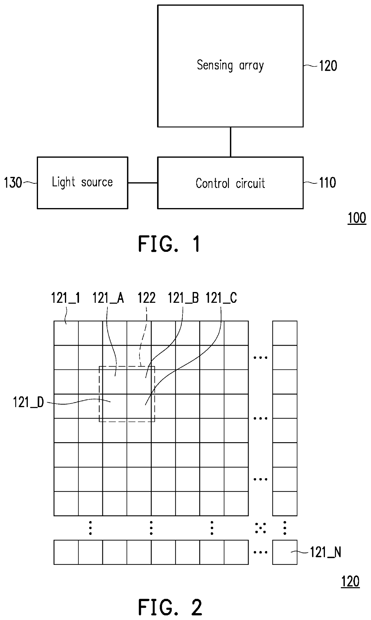
[0017]FIG. 1 is a schematic structural diagram of a light sensor according to an embodiment of the disclosure. FIG. 2 is a schematic diagram of a sensing array according to an embodiment of the disclosure. With reference to FIGS. 1 and 2, a light sensor 100 includes a control circuit 110, a sensing array 120, and a light source 130. The control circuit 110 is coupled to the sensing array 120 and the light source 130. The sensing array 120 includes multiple sensing sub-pixels 121_1 to 121_N, where N is a positive integer. Each of the sensing sub-pixels 121_1 to 121_N includes at least one diode (photodiode). The diode may be a pn junction dio...


PUM

PropertyMeasurementUnit
distanceaaaaaaaaaa
time intervalaaaaaaaaaa
time lengthaaaaaaaaaa

Abstract

A light sensor and a ranging method are provided. The light sensor includes a light source, a sensing sub-pixel, and a control circuit. The sensing sub-pixel includes a diode. The control circuit operates the diode in a Geiger mode or an avalanche linear mode. The control circuit includes a time-to-digital converter. The control circuit sequentially delays multiple light emission times of the light source in consecutive multiple sensing periods according to delay times during the consecutive multiple sensing periods. The control circuit sequentially monitors whether multiple digital values sequentially outputted by the time-to-digital converter corresponding to the consecutive multiple sensing periods have changed. The control circuit calculates a distance value according to the multiple digital values and a corresponding delay sequence when the control circuit determined that the multiple digital values have changed for a first time.

Description

CROSS-REFERENCE TO RELATED APPLICATION[0001]This application claims the priority benefit of U.S. provisional application Ser. No. 63 / 050,120, filed on Jul. 10, 2020, and U.S. provisional application Ser. No. 63 / 058,502, filed on Jul. 30, 2020. The entirety of each of the above-mentioned patent applications is hereby incorporated by reference herein and made a part of this specification.BACKGROUNDTechnical Field[0002]This disclosure relates to a sensing technology, and in particular to a light sensor and a ranging method.Description of Related Art[0003]Currently, there is a high demand for high-sensitivity ranging sensors in various application fields, such as the medical field or the automotive field. In particular, a light sensor that may be used to sense extremely low light is currently one of the main sensor designs under development. However, a ranging result of a ranging sensor is limited by a bin resolution (or also known as a counting resolution) of a digital converter 330, a...

Claims


Application Information

Patent Timeline
Patent Type & Authority Applications(United States)
IPC IPC(8): G01S7/4865G01S7/481G01S7/484G01S17/10
CPCG01S7/4865G01S7/4816G01S17/10G01S7/4814G01S7/484G01S7/4863G01S17/08H01L27/1446G01S7/497G01S7/4868G01S7/4861H01L31/02027G01J1/44G01J2001/442G01J2001/444G01J2001/4466G01S17/14G04F10/005G01J2001/448H01L31/107H01L27/14609
Inventor YIN, PING-HUNGWANG, JIA-SHYANG
Owner GUANGZHOU TYRAFOS SEMICON TECH CO LTD
Why Eureka
Try Eureka