Position measurement system for geostationary artificial satellite

a technology for positioning measurement and artificial satellites, applied in the direction of instruments, cosmonautic vehicles, and reradiation, etc., can solve the problems of inability to re-transmit reference signals, large distance from ground stations to satellites, and substantial equipment costs, etc., and achieve the effect of simple equipmen

Active Publication Date: 2017-05-02
SKY PERFECT JSAT CORPORATION
View PDF24 Cites 1 Cited by
  • Summary
  • Abstract
  • Description
  • Claims
  • Application Information

AI Technical Summary

Benefits of technology

[0015]The present invention enables high-precision ranging of a geostationary artificial satellite, using comparatively simple equipment, and without occupying a transponder band for the purpose of ranging.

Problems solved by technology

However, the distance from the ground station to the satellite is very large, and hence small angle errors exert a significant influence on position measurement precision within a plane that is perpendicular to the line that joins the ground station and the satellite.
Accordingly, a problem arose in that, in order to achieve a practicable degree of precision with one-station ranging, substantial equipment costs are incurred on account of the need for an antenna that has a large diameter (for instance, about 5 m for radio waves in a 12 GHz frequency band) and that is equipped with a high-precision angle control mechanism.
The method of Patent Literature 1 can be expected to afford better precision than one-station ranging, but has a drawback in that part of a transponder, which is to be used for a service, such a broadcasting or communications, must be utilized on account of a reference signal for ranging.
In the case of a satellite (for instance, a spare satellite) for which the transponder that corresponds to the frequency band for ranging is not in use, moreover, a problem arises in that re-transmission of the reference signal is not possible, and ranging itself cannot be carried out.

Method used


Image

  • Position measurement system for geostationary artificial satellite
  • Position measurement system for geostationary artificial satellite
  • Position measurement system for geostationary artificial satellite

Examples


example)

[0047](Calculation Example)

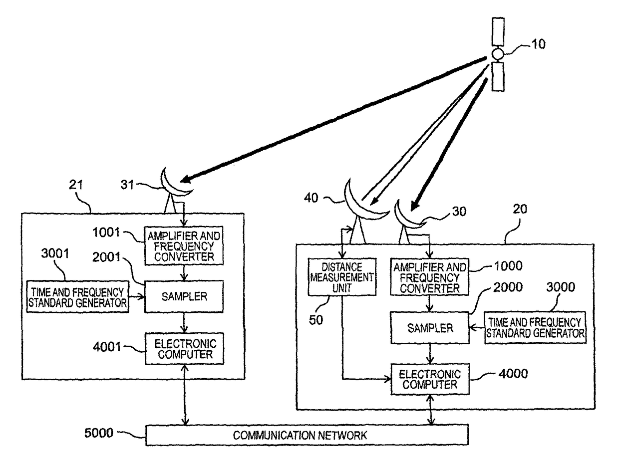
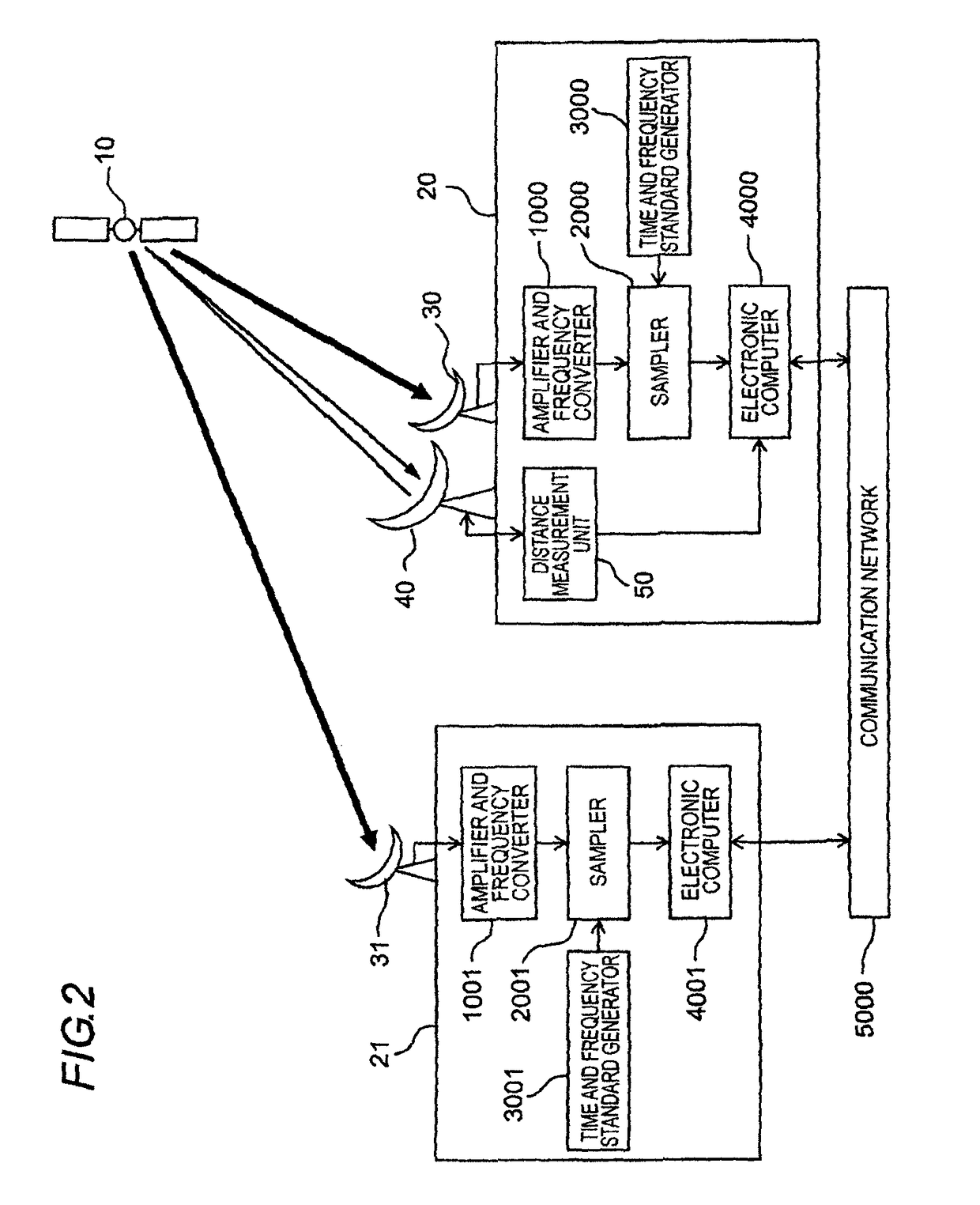
[0048]The 1-PPS output of the time and frequency standard generator is delayed by ΔTgps_rcvr with respect to Coordinated Universal Time (UTC), and the 1-PPS signal outputted by the time and frequency standard generator takes a time ΔT1pps_cable_delay to propagate through the cable and to be inputted to the sampler. Thus, in a case where the times in the sampler are set taking the 1-PPS signal as reference, the times held in the sampler are delayed with respect to UTC by:

ΔTclock_delay=ΔTgps_rcvr+ΔT1pps_cable_delay.

[0049]Taking ΔTclock_delay_x as the delay of the times held in the sampler 2000 of the ground station 20 (X station) with respect to UTC, and ΔTclock_delay_y as the delay of the times held in the sampler 2001 of the ground station 21 (Y station) with respect to UTC, then the clock of the Y station is delayed by ΔTclock with respect to the X station, as follows:

ΔTclock=ΔTclock_delay_y−ΔTclock_delay_x  (Expression 1).

[0050]Herein, Trng_x is the time...


PUM


Abstract

Ground stations 20, 21 receive any signal transmitted by a geostationary artificial satellite 10, and store the reception signal together with the reception time thereof. A difference Δt in reception time of a same signal between the ground station 20 and the ground station 21 is calculated by performing correlation processing of the reception signal of the ground station 20 and the reception signal of the ground station 21. A distance R20 between the ground station 20 and the geostationary artificial satellite 10 is measured by a distance measurement device. A distance R21 between the ground station 21 and the geostationary artificial satellite 10 is calculated on the basis of the distance R20 obtained by measurement and the difference Δt in reception times, as obtained by correlation processing.

Description

TECHNICAL FIELD[0001]The present invention relates to a technology for measuring the position of a geostationary artificial satellite that orbits in outer space.BACKGROUND ART[0002]Geostationary artificial satellites (hereafter, also simply “satellites”) are used in services such as satellite broadcasting and satellite communications. Geostationary artificial satellites circle the earth along a predetermined geostationary orbit that has the same period as that of the earth's rotation. Viewed from the ground, thus, a geostationary artificial satellite appears to stand at the same elevation and azimuth at all times. In actuality, the position of the satellite deviates slightly from the geostationary orbit as a result of forces such as the gravitational pull of the sun / moon / earth, solar radiation pressure and the like that act on the satellite. During operation of the geostationary artificial satellite, therefore, it is necessary to correct periodically deviations from orbit. Specifica...

Claims


Application Information

Patent Timeline
Patent Type & Authority Patents(United States)
IPC IPC(8): G01S5/06B64G1/36B64G1/24B64G3/00G01S5/12G01S5/14
CPCG01S5/06B64G1/242B64G1/36B64G3/00G01S5/14G01S5/12G01S11/02
Inventor SATO, EIJIICHIE, YASUHIDENAGAI, HIROAKI
Owner SKY PERFECT JSAT CORPORATION
Why Eureka
Try Eureka