
Apparatus and method for treatment of post thrombotic syndrome

a technology for thrombotic syndrome and appendix, which is applied in the field of appendix and method for the treatment of post thrombotic syndrome, can solve the problems of increasing the risk of patients with multiple devices during a single procedure, increasing the cost of additional devices, and increasing the risk of patients with multiple devices

Pending Publication Date: 2022-01-20
BARD PERIPHERAL VASCULAR
View PDF0 Cites 3 Cited by
  • Summary
  • Abstract
  • Description
  • Claims
  • Application Information

AI Technical Summary

Benefits of technology

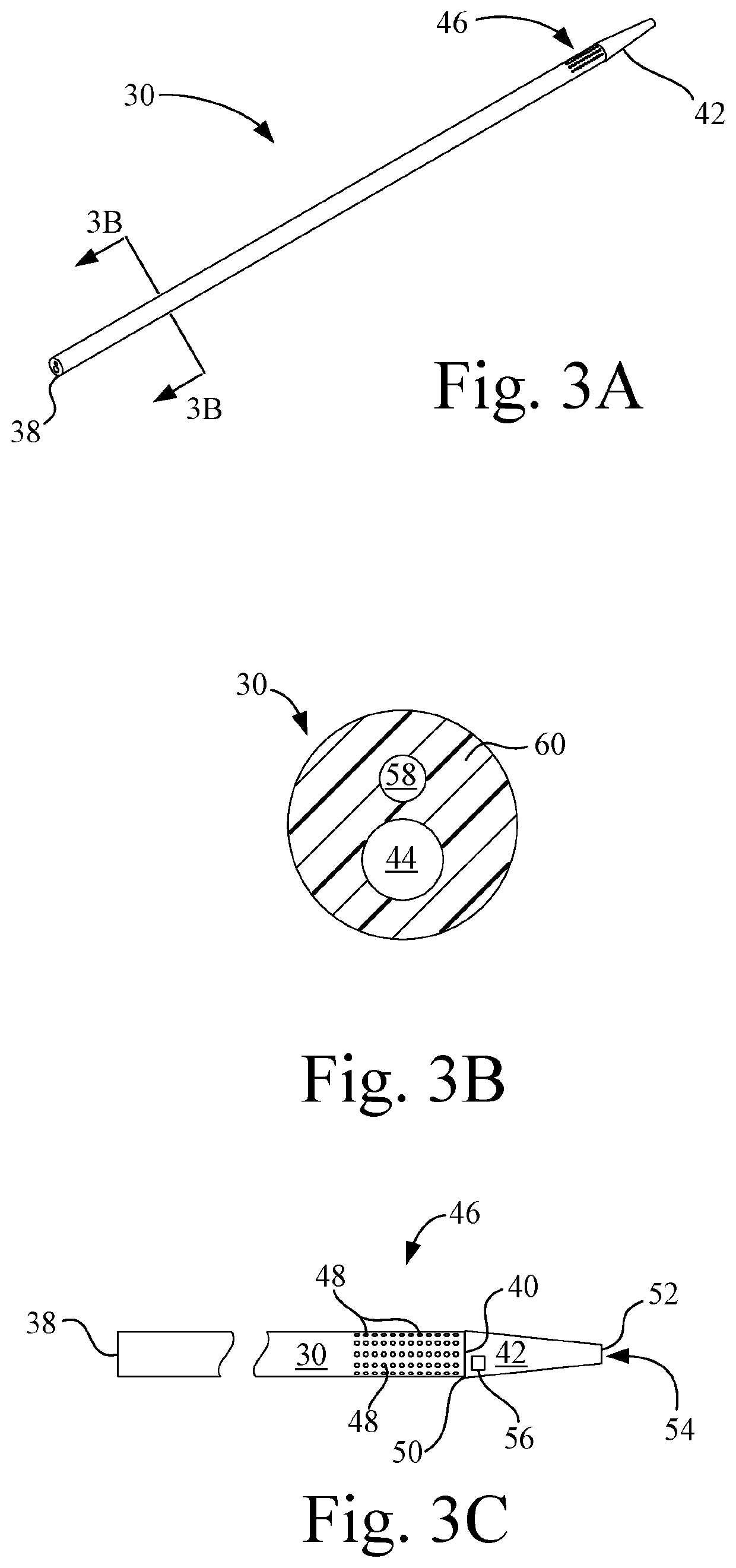
The present invention provides a medical apparatus for the treatment of post thrombotic syndrome. The apparatus includes a sheath and a thrombectomy device. The sheath is movable between an extended sheath position and a retracted sheath position. The thrombectomy device includes a first elongate cannula, a second elongate cannula, a third elongate cannula, and a fourth elongate cannula. The first elongate cannula has a proximal end, a distal end with a distal tip, a guidewire lumen, and a perforated region in fluid communication with the guidewire lumen. The second elongate cannula has a proximal end, a distal end, a second lumen, and a mechanical thrombectomy whisk. The third elongate cannula has a distal end, a third exterior surface, a third proximal end, a third distal end, a third lumen, an inflation passageway, and an inflatable balloon. The fourth elongate cannula has a distal end, a distal tip with a marker, and an expandable embolic filter connected to the distal tip at a location distal to the inflatable balloon. The medical apparatus can be used to treat a thrombus in a vein. The invention also includes a method for using the apparatus to treat a thrombus.

Problems solved by technology

The use of multiple devices during a single procedure requires additional costs associated with the additional devices and additional procedure time.
Furthermore, the use of multiple devices during a procedure increases additional risk to the patient related to the multiple insertions and prolonged procedure time.

Method used


Image

  • Apparatus and method for treatment of post thrombotic syndrome
  • Apparatus and method for treatment of post thrombotic syndrome
  • Apparatus and method for treatment of post thrombotic syndrome

Examples


Embodiment Construction

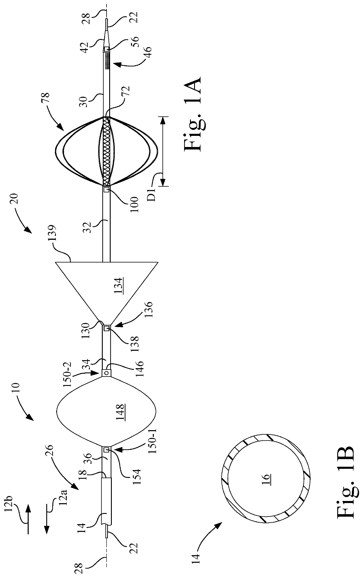
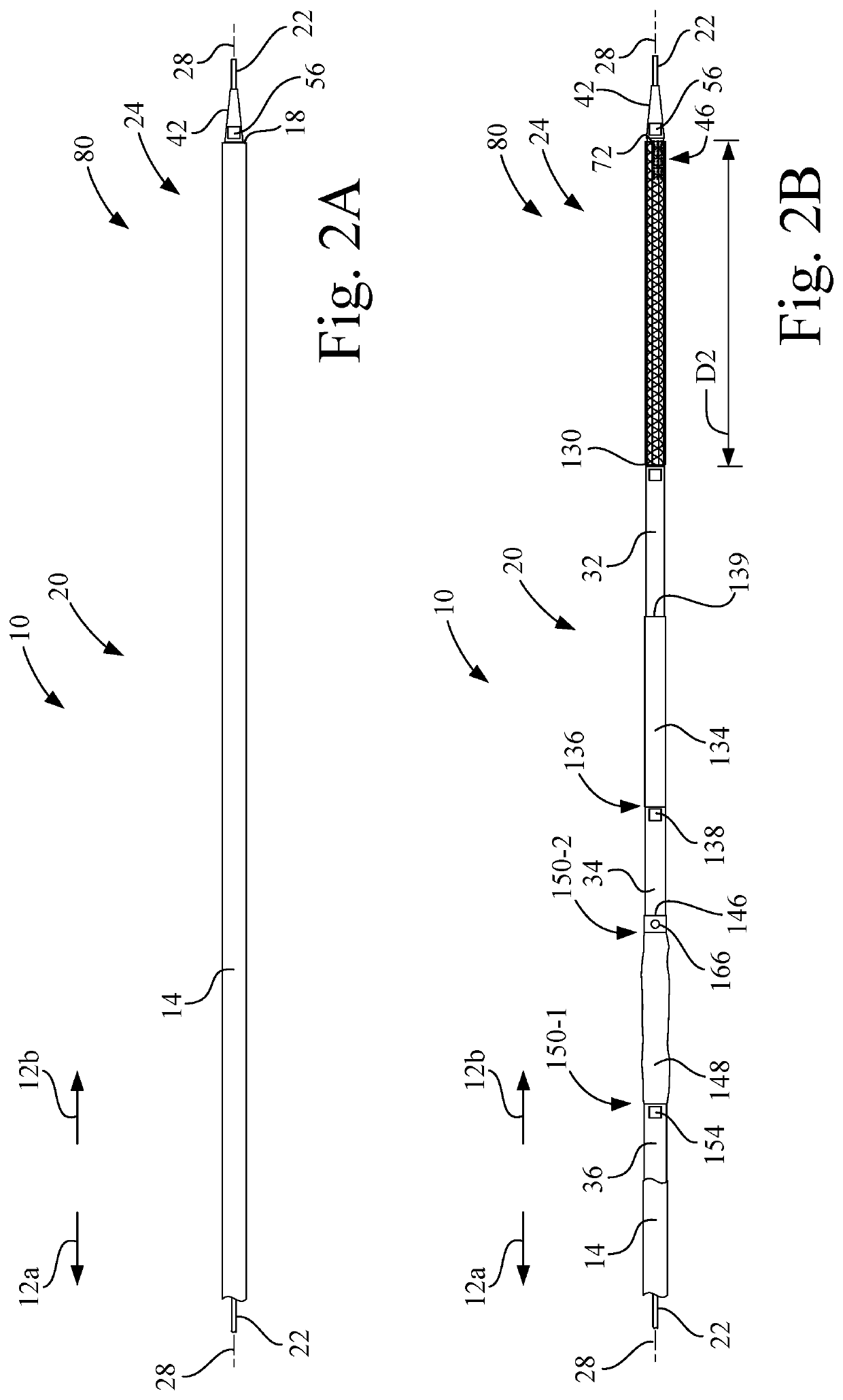
[0048]Referring now to the drawings, and more particularly to FIG. 1A, there is shown a medical apparatus 10 for treating any form of thrombus, including treating post thrombotic syndrome. FIG. 1A includes a proximal direction 12a and a distal direction 12b. The medical apparatus generally includes a sheath 14, which has a sheath lumen 16 and a sheath distal end 18, and a thrombectomy device 20. Thrombectomy device 20 is disposed in the sheath lumen 16, so that thrombectomy device 20 is protected as medical apparatus 10 slides over a guidewire 22. As shown in FIG. 1A and FIGS. 2A-2B, medical apparatus 10 extends along a longitudinal axis 28.

[0049]Sheath 14 is movable between an initial extended sheath position 24, e.g., the position shown in FIGS. 2A-2B, and a retracted sheath position 26, e.g., the position shown in FIG. 1A, to expose thrombectomy device 20. Sheath 14 may be constructed of thermoplastic, e.g., PEBAX® or a metal alloy, e.g., stainless steel or nitinol.

[0050]Thrombec...


PUM


Abstract

A medical apparatus has a thrombectomy device disposed in a sheath lumen of a sheath that is movable between an initial extended position and a retracted position. The thrombectomy device includes a first elongate cannula having a distal tip, a guidewire lumen, and a perforated region, which is proximal to the distal tip and is in fluid communication with the guidewire lumen. A second elongate cannula, which is configured to rotate, has a second lumen and a mechanical thrombectomy whisk, which is proximal to the distal tip. A third elongate cannula has a third exterior surface, a third lumen, an inflation passageway, an inflatable balloon connected to the third exterior surface, and an expandable embolic filter connected to the third exterior surface at a location distal to the inflatable balloon. The first elongate cannula is disposed in the second lumen. The second elongate cannula is disposed in the third lumen.

Description

CROSS-REFERENCE TO RELATED APPLICATIONS[0001]None.TECHNICAL FIELD[0002]The present invention relates generally to an apparatus and method for the treatment of post thrombotic syndrome, and, more particularly, the technology relates to a single medical apparatus for providing mechanical thrombectomy, lytic delivery, and embolic protection.BACKGROUND ART[0003]Currently, physicians must pull multiple devices off the shelf during a single procedure to provide mechanical thrombectomy, lytic infusion, and aspiration during the treatment of post thrombotic syndrome. The use of multiple devices during a single procedure requires additional costs associated with the additional devices and additional procedure time. Furthermore, the use of multiple devices during a procedure increases additional risk to the patient related to the multiple insertions and prolonged procedure time.[0004]What is needed, therefore, is a single device that would provide physicians with the ability to treat a patien...

Claims


Application Information

Patent Timeline
IPC IPC(8): A61B17/221A61B17/22A61B90/00
CPCA61B17/221A61B17/22032A61B90/39A61B2090/3966A61B2017/22079A61B2017/22038A61B90/37A61B2017/22084A61B17/320725A61B2017/320733A61B17/320758A61B2217/007A61B2017/320716A61B2017/22067A61B2090/376A61F2/013
Inventor ERLICK, BENJAMINGERVELER, MATTHEWLEWIS, MICHAELMILLAR, CLAIRESAMPATH KUMARAN, RANJANISIMMONS, BRANDONTESSMER, ALEXANDERTRISTAN, MICHAELTZE, DAVID
Owner BARD PERIPHERAL VASCULAR
Learn More